USER GUIDE AND SPECIFICATIONS NI 6509 The NI 6509 is a 96-bit, high-drive digital input/output (I/O) device for PCI, PXI, and CompactPCI chassis. The NI 6509 features 96 TTL/CMOS-compatible digital I/O lines, 24 mA high-drive output, a watchdog timer, digital filtering, and programmable power-up states. Contents Configuration .......................................................................................... 2 Programming Devices in Software ..................................................
Configuration The NI 6509 device is completely software configurable, so it is not necessary to set jumpers for I/O configuration. The PCI-6509 device is fully compliant with the PCI Local Bus Specification, Revision 2.2, and the PXI-6509 device is fully compliant with the PXI Hardware Specification, Revision 2.1. The PCI/PXI system automatically allocates all device resources, including the base address and interrupt level. The device base address is mapped into PCI memory space.
Programming Devices in Software National Instruments measurement devices are packaged with NI-DAQ driver software, an extensive library of functions and VIs you can call from your application software, such as LabVIEW or LabWindows™/CVI™, to program all the features of your NI measurement devices. Driver software has an application programming interface (API), which is a library of VIs, functions, classes, attributes, and properties for creating applications for your device. NI-DAQ 8.
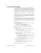
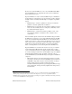
Functional Overview Figure 1 shows the key functional components of the NI 6509 device. 24 mA DIO Tranceivers Port 0 10 MHz Clock Port 1 Flash Memory Port 2 Industrial Digital I/O Control FPGA Port 4 96 DIO 96 DIO Port 6 DIO Lines I/O Connector Port 5 Programmable Power-Up States Watchdog Timer Digital Filtering Data/Control PCI Bus Interface Change Detection Port 7 Data/Control PCI/PXI/CompactPCI Bus Port 3 Port 8 Port 9 Configuration Control Port 10 Port 11 Figure 1.
If you need to clean the DIO device, use a soft, nonmetallic brush. Make sure that the DIO device is completely dry and free from contaminants before returning it to service. Operate the DIO device only at or below Pollution Degree 2. Pollution is foreign matter in a solid, liquid, or gaseous state that can reduce dielectric strength or surface resistivity. The following is a description of pollution degrees: • Pollution Degree 1 means no pollution or only dry, nonconductive pollution occurs.
• Measurement Category II is for measurements performed on circuits directly connected to the electrical distribution system. This category refers to local-level electrical distribution, such as that provided by a standard wall outlet (for example, 115 V for U.S. or 230 V for Europe). Examples of Measurement Category II are measurements performed on household appliances, portable tools, and similar DIO devices.
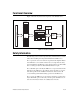
Features The NI 6509 features digital filtering, programmable power-up states, change detection, and a watchdog timer. Digital Filtering Use the digital filter option available on the NI 6509 input lines to eliminate glitches on input data. When used with change detection, filtering can also reduce the number of changes to examine and process. You can configure the digital input channels to pass through a digital filter, and you can control the timing interval the filter uses.
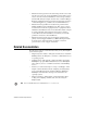
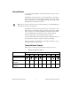
Digital Filtering Example Figure 2 shows a filter configuration with an 800 ns filter interval (400 ns filter clock). External Signal Filter Clock Sample Clock (100 ns) External Signal Sampled H H L L H H L L B H H H H H H H C A Filtered Signal Figure 2. Digital Filtering Example In periods A and B, the filter blocks the glitches because the external signal does not remain steadily high from one rising edge of the filter clock to the next.
Change Detection You can program the NI 6509 to send an interrupt when a change occurs on any input line. The NI 6509 can monitor changes on selected input lines or on all input lines. It can monitor for rising edges (0 to 1), falling edges (1 to 0), or both. When an input change occurs, the NI 6509 generates an interrupt, and the NI-DAQ driver then notifies the software. Excessive change detections can affect system performance. Use digital filtering to minimize the effects of noisy input lines.
This example assumes the following line connections: • Bits 7, 6, 5, and 4 are connected to data lines from a four-bit TTL output device. The NI 6509 detects any change in the input data so you can read the new data value. • Bit 1 is connected to a limit sensor. The NI 6509 detects rising edges on the sensor, which correspond to over-limit conditions. • Bit 0 is connected to a switch. The software can react to any switch closure, which is represented by a falling edge.
Digital I/O Connections The 100-pin high-density SCSI connector on the NI 6509 provides access to 96 digital inputs and outputs. Use this connector to connect to external devices, such as solid-state relays (SSRs) and LEDs. For easy connection to the digital I/O connector, use the National Instruments SH100-100-F shielded digital I/O cable with the SCB-100 connector block, or use the R1005050 ribbon cable with the CB-50 or CB-50LP connector block.
P2.7 1 51 P8.7 P5.7 2 52 P11.7 P2.6 3 53 P8.6 P5.6 4 54 P11.6 P2.5 5 55 P8.5 P5.5 6 56 P11.5 P2.4 7 57 P8.4 P5.4 8 58 P11.4 P2.3 9 59 P8.3 P5.3 10 60 P11.3 P2.2 11 61 P8.2 P5.2 12 62 P11.2 P2.1 13 63 P8.1 P5.1 14 64 P11.1 P2.0 15 65 P8.0 P5.0 16 66 P11.0 P1.7 17 67 P7.7 P4.7 18 68 P10.7 P1.6 19 69 P7.6 P4.6 20 70 P10.6 P1.5 21 71 P7.5 P4.5 22 72 P10.5 P1.4 23 73 P7.4 P4.4 24 74 P10.4 P1.3 25 75 P7.3 P4.3 26 76 P10.3 P1.
R1005050 Connector Figure 4 shows the pin assignments for the R1005050 cable when connecting to the NI 6509 device. The naming convention for each pin is PX.Y, where X is the port (P) number, and Y is the line number or name. Positions 1 through 50 P2.7 P2.6 P2.5 P2.4 P2.3 P2.2 P2.1 P2.0 P1.7 P1.6 P1.5 P1.4 P1.3 P1.2 P1.1 P1.0 P0.7 P0.6 P0.5 P0.4 P0.3 P0.2 P0.1 P0.0 +5 V Positions 51 through 100 1 3 5 2 4 6 P5.7 P8.7 P5.6 P8.6 P5.5 P8.5 7 9 11 13 15 17 19 21 8 10 12 14 16 18 20 22 P5.4 P8.
Signal Descriptions Table 3 lists the signals and descriptions for all signals available on the NI 6509 device. Table 3. NI 6509 Signal Descriptions Pin Signal Name Description MSB LSB 1, 3, 5, 7, 9, 11, 13, 15 P2.<7..0> Bi-directional data lines for port 2 P2.7 P2.0 2, 4, 6, 8, 10, 12, 14, 16 P5.<7..0> Bi-directional data lines for port 5 P5.7 P5.0 17, 19, 21, 23, 25, 27, 29, 31 P1.<7..0> Bi-directional data lines for port 1 P1.7 P1.0 18, 20, 22, 24, 26, 28, 30, 32 P4.<7..
Power Connections Pins 49 and 99 supply +5 V power to the I/O connector. The I/O connector power has a fuse for overcurrent protection. This fuse is not customer replaceable. If the fuse is blown, return the device to NI for repair. Caution Do not connect the +5 V power pin directly to ground or to any other voltage source on any other device. Doing so may permanently damage the NI 6509 device and the computer.
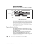
+5 V LED 41 43 Port 0 45 P0<3..0> 47 67 TTL Signal 69 Port 7 71 P7<7..4> 73 +5 V 50, 100 GND NI 6509 Figure 5. NI 6509 Signal Connections Protecting Inductive Loads When inductive loads are connected to outputs, a large counter-electromotive force may occur at switching time because of the energy stored in the inductive load. These flyback voltages can damage the outputs and/or the power supply.
PX.Y Load GND NI 6509 Flyback Diode for Inductive Loads Figure 6. Limiting Flyback Voltages at the Inductive Load Sinking and Sourcing Examples The following sections provide examples of driving a relay less than 24 mA, driving a relay greater than 24 mA, and driving solid-state relays. Driving a Relay <24 mA Figures 7 and 8 show examples of connecting the NI 6509 to a relay that does not require more than 24 mA of current. Vcc PX.Y GND NI 6509 Figure 7.
Driving a Relay >24 mA Figures 9 and 10 are examples of connecting the NI 6509 to a relay that requires more than 24 mA of current. These examples use an additional transistor circuit. Vcc PX.Y GND NI 6509 Figure 9. NI 6509 Sinking Connection Example, >24 mA Vcc PX.Y GND NI 6509 Figure 10. NI 6509 Sourcing Connection Example, >24 mA Driving SSRs Figure 11 shows an example of connecting the NI 6509 to a solid-state relay (SSR). + Load VAC – PX.Y SSR Load GND NI 6509 Figure 11.
Accessories National Instruments offers the following products for use with the NI 6509. Cable (Part Number) Accessory (Part Number) SH100-100-F shielded cable (185095) SCB-100 connector block (776990) R1005050 ribbon cable (182762) CB-50 connector block, DIN-rail mount (776164) CB-50LP connector block, panel mount (777101) For more information about optional equipment available from National Instruments, refer to the National Instruments catalog or visit ni.com.
Power-on state ........................................Inputs high-Z (default), user-selectable input, output 1 or 0 Data transfers ..........................................Interrupts, programmed I/O I/O connector ..........................................100-pin female 0.050 series SCSI Digital Logic Levels Input Signals The maximum input logic high and output logic high voltages assume a Vcc supply voltage of 5.0 V. Given a Vcc supply voltage of 5.
Physical Characteristics Dimensions (without connectors) PCI-6509 ......................................... 12.4 cm × 9.7 cm (4.9 in. × 3.8 in.) PXI-6509......................................... 16.0 cm × 10.0 cm (6.3 in. × 3.9 in.) Weight PCI-6509 ......................................... 70.87 g (2.5 oz) PXI-6509......................................... 172.9 g (6.1 oz) Environmental The NI 6509 device is intended for indoor use only. Operating Environment Ambient temperature range....................
Shock and Vibration (PXI-6509 Only) Operational shock ...................................30 g peak, half-sine, 11 ms pulse (tested in accordance with IEC-60068-2-27; test profile developed in accordance with MIL-PRF-28800F) Random vibration 5 to 500 Hz, 0.3 grms .....................Operating 5 to 500 Hz, 2.4 grms .....................Nonoperating Random vibration is tested in accordance with IEC-60068-2-64. The nonoperating test profile exceeds the requirements of MIL-PRF-28800F, Class 3.
CE Compliance This product meets the essential requirements of applicable European Directives, as amended for CE marking, as follows: • 2006/95/EC; Low-Voltage Directive (safety) • 2004/108/EC; Electromagnetic Compatibility Directive (EMC) Refer to the Declaration of Conformity (DoC) for this product for any additional regulatory compliance information. To obtain the DoC for this product, visit ni.