IMAQ TM NI 1450 Series Compact Vision System User Manual NI 1450 Series Compact Vision System User Manual June 2003 Edition Part Number 323610A-01
Support Worldwide Technical Support and Product Information ni.
Important Information Warranty The NI 1450 Series Compact Vision System is warranted against defects in materials and workmanship for a period of one year from the date of shipment, as evidenced by receipts or other documentation. National Instruments will, at its option, repair or replace equipment that proves to be defective during the warranty period. This warranty includes parts and labor.
Compliance FCC/Canada Radio Frequency Interference Compliance Determining FCC Class The Federal Communications Commission (FCC) has rules to protect wireless communications from interference. The FCC places digital electronics into two classes. These classes are known as Class A (for use in industrial-commercial locations only) or Class B (for use in residential or commercial locations). All National Instruments (NI) products are FCC Class A products.
Conventions The following conventions are used in this manual: » The » symbol leads you through nested menu items and dialog box options to a final action. The sequence File»Page Setup»Options directs you to pull down the File menu, select the Page Setup item, and select Options from the last dialog box. This icon denotes a tip, which alerts you to advisory information. This icon denotes a note, which alerts you to important information.
Contents Chapter 1 NI 1450 Overview About the NI 1450 Series Compact Vision System.......................................................1-1 Hardware Overview .......................................................................................................1-1 Available Camera Bandwidth ........................................................................................1-3 Software Overview ........................................................................................................
Contents LabVIEW Real-Time with the Vision Development Module: Setting up the Development Computer.............................................................................................. 2-15 Installing LabVIEW Real-Time, Vision Development Module, and NI-IMAQ for IEEE 1394 Cameras ....................................................... 2-15 Configuring the IP Address using LabVIEW Real-Time ............................... 2-16 Downloading Software onto the NI 1450 ...................................
Contents Pulse Width .......................................................................................4-5 Trigger Polarity .................................................................................4-5 Quadrature Encoder.........................................................................................4-6 Product Selection Port .....................................................................................4-7 Using ISO Input 5 as a Latch .............................................
1 NI 1450 Overview This chapter provides an overview of the features and components on the National Instruments 1450 Series Compact Vision System. About the NI 1450 Series Compact Vision System The NI 1450 Series Compact Vision System is an easy-to-use, distributed, real-time imaging system that acquires, processes, and displays images from IEEE 1394 cameras conforming to the IIDC 1394-based Digital Camera Specification, Version 1.30.
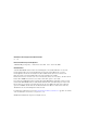
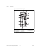
Chapter 1 NI 1450 Overview Figure 1-1 shows the NI 1450 front panel. 1 NI 1454 Compact Vision System 11 2 3 4 10 5 9 6 8 7 1 2 3 4 Power LED Status LED Isolated Digital Input TTL Digital Outputs 5 6 7 8 IEEE 1394a Ports 9 VGA TTL I/O and Isolated I/O 10 RS-232 Serial Reset Button 11 RJ-45 Ethernet Port DIP Switches Figure 1-1. NI 1450 Series Compact Vision System Front Panel NI 1450 Series Compact Vision System User Manual 1-2 ni.
Chapter 1 NI 1450 Overview Available Camera Bandwidth The IEEE 1394 bus provides a fixed amount of bandwidth that is shared among the three IEEE 1394a ports on the NI 1450. These ports provide direct connection to up to three DCAM-compliant IEEE 1394 cameras, depending on the amount of bandwidth each camera requires. Higher frame rates and larger image sizes require a higher data transfer rate and use more bandwidth.
Chapter 1 NI 1450 Overview Software Overview Programming the NI 1450 Series Compact Vision System requires the NI-IMAQ for IEEE 1394 Cameras driver software, version 1.5 or later, to control the hardware and one of the following application software packages to process images. • NI Vision Builder for Automated Inspection (AI), version 2.0 or later—To configure solutions to common inspection tasks • LabVIEW Real-Time (RT), version 7.0 or later, with the Vision Development Module, version 7.
Chapter 1 NI 1450 Overview National Instruments Application Software Vision Builder for Automated Inspection National Instruments Vision Builder for Automated Inspection (AI) is configurable machine vision software that you can use to prototype, benchmark, and deploy applications. NI Vision Builder AI does not require programming, but is scalable to LabVIEW RT.
Chapter 1 NI 1450 Overview Vision Assistant is an interactive prototyping tool for machine vision and scientific imaging developers and is included with the Vision Development Module. With Vision Assistant, you can prototype vision applications quickly and test how various vision image processing functions work. For information about how to use the Vision Development Module with LabVIEW RT, refer to the IMAQ Vision for LabVIEW User Manual. NI 1450 Series Compact Vision System User Manual 1-6 ni.
2 Setup and Configuration This chapter provides instructions for connecting the NI 1450 Series Compact Vision System hardware. This chapter also includes instructions for installing software, configuring an IP address, and acquiring an initial image using the application software. Required Items The following items are necessary for connecting the NI 1450.
Chapter 2 Setup and Configuration ❑ 4-position power connector—required if you are not using the NI desktop power supply ❑ 10 m 10/100Base-T Ethernet cable (part number 189174-10)—standard CAT 5 10/100Base-T Ethernet cable for connecting the NI 1450 to a network port. To connect the NI 1450 directly to a local development computer, use an Ethernet crossover cable. Note To maintain signal integrity, the Ethernet cable length must be no longer than 100 m.
Chapter 2 Setup and Configuration • Digital I/O cable and vertical DIN rail terminal block (part number 778791-01) • 75 Ω SMB 111 coaxial cable (part number 763422-01)— SMB to BNC cable for connecting to triggers and light sources • 10 m Ethernet crossover cable (part number 187375-10)—for connecting the NI 1450 directly to the development computer Documentation The documentation resources listed in this section ship with the NI 1450 and the application software.
Chapter 2 Setup and Configuration LabVIEW Real-Time Module and Vision Development Module Documents • NI Vision Assistant Help • NI Vision Assistant Tutorial • IMAQ Vision Concepts Manual • IMAQ Vision for LabVIEW User Manual • IMAQ Vision for LabVIEW Help • LabVIEW Real-Time Module documentation Safety Information The following paragraphs contain important safety information you must follow when installing and operating the device.
Chapter 2 Setup and Configuration foreign matter—solid, liquid, or gas—that may reduce dielectric strength or surface resistivity. Pollution degrees are listed below. • Pollution Degree 1—No pollution or only dry, nonconductive pollution occurs. The pollution has no effect. • Pollution Degree 2—Normally only nonconductive pollution occurs. Occasionally, nonconductive pollution becomes conductive because of condensation. • Pollution Degree 3—Conductive pollution or dry, nonconductive pollution occurs.
Chapter 2 Setup and Configuration equipment, circuits powered by regulated low-voltage sources, and electronics. • Installation Category II is for measurements performed on circuits directly connected to the electrical distribution system. This category refers to local-level electrical distribution, such as that provided by a standard wall outlet (e.g., 115 V for U.S. or 230 V for Europe).
Chapter 2 Setup and Configuration Set Up the Hardware Set Up the Development Computer Using Vision Builder AI or Set Up the Development Computer Using LabVIEW Real-Time with the Vision Development Module Acquire an Image Using Vision Builder AI or Acquire an Image Using LabVIEW Real-Time with the Vision Development Module Figure 2-1. Connection Sequence • Set up the hardware—This section explains how to connect a camera, monitor, and power supply to the NI 1450.
Chapter 2 Setup and Configuration Subnet Considerations To configure the NI 1450, it must reside on the same subnet as the development computer. Once the NI 1450 is configured, other subnets can access and use it. To use the NI 1450 on a subnet other than the one the development computer is on, first connect and configure it on the same subnet as the development computer. Next, physically move it to the other subnet and reassign an IP address.
Chapter 2 Setup and Configuration If your camera requires an external power supply, connect it to the camera and verify that the camera is powered on. 3. Plug in and power on the monitor. 1 2 1 VGA Cable 2 IEEE 1394 Cable Figure 2-2. Basic Hardware Setup Wiring Power to the NI 1450 This section describes how to connect the NI desktop power supply. For instructions on how to connect a separate main supply, refer to the Connecting to a Separate Main Supply section.
Chapter 2 Setup and Configuration The NI 1450 ships with a factory-installed startup program that, when the NI 1450 is connected to a camera and powered on, acquires images and displays them on the monitor. If these images from the camera display on the monitor, continue to the Connecting the NI 1450 to the Development Computer section. If the images from the camera are not displayed on the monitor, refer to Appendix A, Troubleshooting.
Chapter 2 Setup and Configuration The NI 1450 ships with a 4-position power connector that plugs directly into the power input connector on the NI 1450. To wire power to the 4-position connector, complete the following steps: 1. Wire the voltage output of the 24 VDC ±10% power supply to the main voltage input, labeled V, on the 4-position connector. 2. Wire the common (ground) output of the power supply to the common input, labeled C, on the 4-position connector.
Chapter 2 Setup and Configuration 3 1 1 2 3 2 Standard Ethernet Cable Connecting from the NI 1450 to an Ethernet Hub Standard Ethernet Cable Connecting from an Ethernet Hub to the Development Computer Ethernet Hub or Other Network Port Figure 2-4.
Chapter 2 Setup and Configuration The following items are necessary for setting up the development computer. ❑ Vision Builder AI software, version 2.0 or later ❑ NI-IMAQ for IEEE 1394 Cameras driver software, version 1.5 or later Installing Vision Builder AI and NI-IMAQ for IEEE 1394 Cameras This section describes how to install the Vision Builder AI software and the NI-IMAQ for IEEE 1394 Cameras driver software onto the development computer.
Chapter 2 Setup and Configuration To uniquely identify unconfigured NI 1450s, connect and configure one NI 1450 at a time. Tip 4. Click Configure to launch the Vision Builder AI Remote Target Configuration Wizard. 5. In the Identification window, enter a name for the NI 1450 in the Name field and a description of the NI 1450 in the Description field. Note Device names are limited to 15 characters with no spaces or special characters. The first and last characters must be alphanumeric. 6.
Chapter 2 Setup and Configuration LabVIEW Real-Time with the Vision Development Module: Setting up the Development Computer This section describes the sequence for installing the application and driver software on the development computer, obtaining an IP address, installing software on the NI 1450, and configuring the NI 1450 to acquire an image using LabVIEW Real-Time. This section applies only to LabVIEW Real-Time users.
Chapter 2 Setup and Configuration 7. Insert the NI-IMAQ for IEEE 1394 Cameras CD into the CD-ROM drive. Note If you select the custom software installation, make sure to install the support for the NI 1450 Series Compact Vision System. 8. When the splash screen appears, click Install NI-IMAQ for IEEE 1394 Cameras and follow the setup instructions. 9. When prompted, click Yes to reboot the development computer.
Chapter 2 Setup and Configuration Downloading Software onto the NI 1450 1. In the MAX configuration window, click the Software tab. This window displays the status of the software on the NI 1450. 2. Click the Install Software button. 3. Select the software to download. For initial installation, make sure all checkboxes are selected. 4. Click OK. 5. When prompted, click Yes to reboot the NI 1450. This process takes several seconds.
3 LEDs, DIP Switches, and Connectors This chapter provides information about the location and functionality of the LED indicators, DIP switches, and connectors on the NI 1450. The Connectors section provides signal names and descriptions for each connector. LED Indicators Figure 3-1 shows the location of the POWER OK and STATUS LEDs on the NI 1450. STATUS NI 1454 Compact Vision System POWER OK Figure 3-1.
Chapter 3 LEDs, DIP Switches, and Connectors POWER OK LED Under normal operating conditions, the POWER OK LED remains green while the NI 1450 is powered on. A green POWER OK LED indicates that NI 1450 main power is receiving power and that the NI 1450 is not in a fault state. A red POWER OK LED indicates that the NI 1450 has shut down because of a fault state. A fault state occurs when the user shutdown input is asserted, the processor overheats, or the watchdog timer expires.
Chapter 3 LEDs, DIP Switches, and Connectors NI 1454 Compact Vision System Figure 3-2. ACT/LINK and 100 Mbps LEDs DIP Switches This section describes the SAFE MODE, IP RESET, NO APP, and USER 1 DIP switches on the NI 1450. To enable a DIP switch, move it to the ON (left) position and then reset the NI 1450 by pressing the RESET button for at least two seconds. Note You must reset the NI 1450 in order for the setting change to occur.
Chapter 3 LEDs, DIP Switches, and Connectors Figure 3-3 shows the location of the DIP switches on the NI 1450. NI 1454 Compact Vision System ON Figure 3-3. DIP Switches SAFE MODE Switch To boot the NI 1450 in Safe mode, move the SAFE MODE switch to the ON position and reset the NI 1450. Use safe mode to reconfigure TCP/IP settings and to download or update software from the development computer.
Chapter 3 LEDs, DIP Switches, and Connectors IP RESET Switch To clear the NI 1450 IP settings, move the IP RESET switch to the ON position and reset the NI 1450. Use IP RESET to reset the TCP/IP settings when moving the system from one subnet to another or when the current TCP/IP settings are invalid. Resetting the NI 1450 with the IP RESET switch in the ON position resets the IP address to 0.0.0.0.
Chapter 3 LEDs, DIP Switches, and Connectors Connectors This section describes the connectors on the NI 1450 and includes pinouts and signal descriptions for each connector. Table 3-1 summarizes the functions of the connectors on the NI 1450. Table 3-1.
Chapter 3 LEDs, DIP Switches, and Connectors Figure 3-4 shows the power connector on the NI 1450, and Table 3-2 describes each terminal on the connector. POWER Ciso POWER Viso (5-30 VDC) C Ciso Viso (5-30 VDC) C V (24 VDC ±10%) V (24 VDC ±10%) Figure 3-4. Power Connector Table 3-2.
Chapter 3 LEDs, DIP Switches, and Connectors 1 POWER Ciso Viso (5-30VDC) 2 C V (24VDC ±10%) 1 Grounding Lug 2 Power Connector Figure 3-5. Grounding Lug on the NI 1450 IEEE 1394 The IEEE 1394 connectors on the NI 1450 provide a reliable, high-frequency connection between the NI 1450 and to up to three DCAM-compatible IEEE 1394 cameras. For information about the amount of bandwidth available for connecting cameras, refer to the Available Camera Bandwidth section of Chapter 1, NI 1450 Overview.
Chapter 3 LEDs, DIP Switches, and Connectors NI 1454 Compact Vision System 1 6 11 5 10 15 Figure 3-6. VGA Connector Table 3-3.
Chapter 3 LEDs, DIP Switches, and Connectors COM1 COM1 is a high-speed RS-232 (DTE) serial port used for connecting to serial devices, such as PLCs, scanners, and lighting devices. Note The Serial Port VIs access COM1 as Port 0. Figure 3-7 shows the locations of the COM1 DSUB 9-pin connector. Refer to Table 3-4 for COM1 signal names and descriptions NI 1454 Compact Vision System 5 9 1 6 Figure 3-7. COM1 DSUB 9-Pin Connector Table 3-4.
Chapter 3 LEDs, DIP Switches, and Connectors Ethernet The Ethernet port on the NI 1450 provides connection between the NI 1450 and the development computer, either directly or through a network port. The NI 1450 automatically detects the speed of the connection and configures itself accordingly. If you are connecting the NI 1450 to the development computer through a network port, use a standard Ethernet cable. To connect the NI 1450 directly to the development computer, use an Ethernet crossover cable.
Chapter 3 LEDs, DIP Switches, and Connectors For detailed information about digital I/O functionality and recommended use cases, refer to Chapter 4, Digital I/O Functionality. Note Isolated inputs are compatible with 5 V logic if the external circuit meets the voltage and current requirements listed in Appendix B, Specifications. NI 1454 Compact Vision System 44 30 15 31 16 1 Figure 3-8.
Chapter 3 LEDs, DIP Switches, and Connectors Table 3-5.
Chapter 3 LEDs, DIP Switches, and Connectors Table 3-5.
4 Digital I/O Functionality This chapter describes the primary functions of the digital inputs and outputs on the NI 1450 Series Compact Vision System. This chapter also includes guidelines for connecting the digital I/O and for setting up a typical NI 1450 system. Overview The digital I/O functions are accessible through 2 TTL inputs, 10 TTL outputs, 13 isolated inputs, and 4 isolated outputs.
Chapter 4 Digital I/O Functionality TTL Inputs and Outputs TTL is a fast-switching 5 V digital signaling standard commonly used for applications that require high precision, such as camera triggering. TTL inputs and outputs do not require a separate power supply. Caution Do not connect voltage or current sources to TTL outputs. Doing so could damage the NI 1450. Table 4-1 summarizes the TTL inputs and outputs available on the NI 1450. Table 4-1.
Chapter 4 Digital I/O Functionality 44-Pin DSUB on NI 1450 Pin Number 37-Pin Terminal Block Pin Number Table 4-2.
Chapter 4 Digital I/O Functionality Timed Pulse Output The NI 1450 is capable of timed pulse output on six different digital outputs, which provides precise control over time-critical signals, such as camera exposure. This section describes the various uses for the timed pulse output and the parameters you can set to control these outputs.
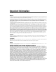
Chapter 4 Digital I/O Functionality Figure 4-1 shows an output pulse when a trigger is selected. Trigger Input Output Pulse Figure 4-1. Output Pulse When Trigger Is Selected Pulse Modes Each pulse generator has a Start and a Stop mode. Configure the pulse generator when in Stop mode and then set it to Start mode. Pulse Delay Pulse delay is the amount of time between a trigger and the first (assertion) edge of an output pulse.
Chapter 4 Digital I/O Functionality Delay Width Trigger Pulse Figure 4-2. High Pulse with Rising Edge Trigger Figure 4-3 shows how to create a high and low pulse train with a microsecond delay and width. High Pulse Train Delay Width Delay Width Low Pulse Train Software Start Figure 4-3. High and Low Pulse Trains Quadrature Encoder The quadrature encoder uses ISO Input 6 for its Phase A input and ISO Input 7 for its Phase B input. Encoder speed is limited by the speed of the isolated inputs.
Chapter 4 Digital I/O Functionality Figure 4-4 shows a rising edge trigger and a low pulse with a quadrature encoder delay and a microsecond width. Trigger Low Pulse Delay Width Phase A Phase B Figure 4-4. Rising Edge Trigger, Low Pulse with a Quadrature Encoder Delay Product Selection Port The product selection port consists of a group of five isolated digital inputs that the software running on the NI 1450 reads simultaneously.
Chapter 4 Digital I/O Functionality Table 4-3 lists the product selection ports. Table 4-3. Product Selection Port Function External Connection Data(5), rising edge latch ISO Input 5 Data(4) ISO Input 4 Data(3) ISO Input 3 Data(2) ISO Input 2 Data(1) ISO Input 1 Data(0) ISO Input 0 General-Purpose I/O General-Purpose Inputs General-purpose inputs are available as both TTL and isolated inputs. At any time, the software running on the NI 1450 can read these inputs.
Chapter 4 Digital I/O Functionality An example of using general-purpose outputs is driving a relay that turns on an Inspection in Progress light for an operator to see while the inspection sequence is running.
Chapter 4 Digital I/O Functionality Disabling Shutdown Mode To disable Shutdown mode once it is enabled, remove Shutdown mode from the software script and reset the NI 1450. To reset the system, press the RESET button on the NI 1450 front panel for at least two seconds. Note For prototyping when equipment is unavailable, you can wire from Viso to ISO Input 11 to simulate external equipment that indicates to the NI 1450 to operate normally.
Chapter 4 Digital I/O Functionality Overheat Operating the NI 1450 outside of its temperature specifications may cause the NI 1450 to overheat. Refer to Appendix B, Specifications, for temperature specifications. In the event of an overheat, all NI 1450 operation halts and the POWER OK LED turns red. If Shutdown mode is enabled, the outputs go to the user-defined shutdown states. Table 4-4.
Chapter 4 Digital I/O Functionality Sourcing Output Device Viso Vcc Input Current Limiter Ciso NI 1450 Figure 4-5. Example of Connecting an Isolated Input to a Sourcing Output Device Wiring an Isolated Output to an External Load The digital output circuit sources current to external loads, as shown in the example in Figure 4-6. The maximum output current of this circuit is 100 mA. Viso Vcc Digital Output Load Ciso NI 1450 Figure 4-6.
Chapter 4 Digital I/O Functionality Protecting Inductive Loads When an inductive load, such as a relay or solenoid, is connected to an output, a large counter-electromotive force may occur at switching time due to energy stored in the inductive load. This flyback voltage can damage the outputs and the power supply. To limit flyback voltages at the inductive load, install a flyback diode across the load. Mount the flyback diode as close to the load as possible.
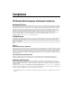
Chapter 4 Digital I/O Functionality TRIG 1 75 Ω TRIG 1 SMB RG-179 Coaxial Cable Receiving Equipment 44-Pin DSUB TTL OUT(0) 118 Ω 3 2 Receiving Equipment +5 V 62 kΩ TTL IN(0) 16 17 RS Transmitting Equipment NI 1450 Figure 4-8. Example Connections When connecting to TTL inputs on the NI 1450 device, match the output impedance of the transmitting device to the characteristic impedance of the cable.
Chapter 4 Digital I/O Functionality Table 4-5 summarizes a typical single-camera configuration. Table 4-5. Typical Single-Camera System Setup Signal Name Signal Type Purpose TRIG 0 Isolated input Trigger input from proximity sensor or external device TRIG 1 Timed pulse TTL output Exposure start and control signal to camera TRIG 2 Timed pulse TTL output Strobe light control Figure 4-9 shows a typical single-camera setup.
5 Deployment This chapter provides guidelines for connecting the NI 1450 Series Compact Vision System to a network. Connecting Multiple NI 1450s An Ethernet connection between the development computer and the NI 1450 allows you to assign an IP address, configure the NI 1450, download inspection tasks, and remotely monitor an ongoing inspection. As with all Ethernet devices, you can connect multiple NI 1450s to the same network, as shown in Figure 5-1. Figure 5-1.
Chapter 5 Deployment To connect multiple NI 1450s to the same network, each NI 1450 must have a unique IP address. By default, the configuration utility running on the development computer displays each NI 1450 that exists on the subnet. To add entries for NI 1450s that exist on other subnets, you must know the IP address assigned to each NI 1450. This feature allows remote configuration, programming, and monitoring of any NI 1450 not protected by a firewall or user password.
Chapter 5 Deployment Figure 5-3. NI 1450 Series Compact Vision System Connected to a Monitor At any time, you can reconnect the host machine to the NI 1450 and remotely monitor progress.
A Troubleshooting This appendix provides instructions for troubleshooting the NI 1450. Software Configuration Problems NI 1450 Does Not Appear in MAX or in Vision Builder AI Possible causes and solutions: • Verify that there is power to the NI 1450 and that both the NI 1450 and the development computer are properly connected to the network. The POWER OK LED should be lit. When you click Browse, the ACT/LINK LED on the NI 1450 should flash to indicate that communications are taking place.
Appendix A Troubleshooting • Another device on the network is using the IP address assigned to the NI 1450. Either remove or reconfigure the other device, or reconfigure the NI 1450 IP address. • The DIP switch settings on the NI 1450 may be invalid, such as all switches set to the ON position. Change the DIP switch settings and reset the NI 1450 by pressing the RESET button on the NI 1450 for at least two seconds.
Appendix A • Watchdog expired while configured for the system shutdown option – • Troubleshooting Determine if the interval between watchdog resets is insufficient for the processing time. Check the software to determine if it could monopolize the processor. Processor overheat – Make sure you are operating the NI 1450 in compliance with the temperature specifications in Appendix B.
Appendix A Troubleshooting Table A-1. STATUS LED Flashes and Corresponding Error Conditions Number of Flashes Error Condition 0 (stays lit) The NI 1450 has detected an internal error. Contact National Instruments for assistance. 1 The NI 1450 is unconfigured. 2 The NI 1450 has detected an error in its software. This usually occurs when an attempt to upgrade the firmware is interrupted. Repeat the firmware upgrade process. 3 The NI 1450 is in Safe mode.
B Specifications This appendix lists the specifications of the NI 1450 Series Compact Vision System. These specifications are typical at 25 °C, unless otherwise noted. Power Requirements Main supply voltage............................... 24 VDC ±10% Power (excluding cameras)............. 12 W, typical 22 W, maximum 1394 bus power ............................... 18 W, maximum (shared by all three ports) Isolated supply1 ...................................... 5 to 30 VDC Memory SDRAM .....................
Appendix B Specifications TTL Inputs and Outputs Digital logic levels Level Minimum Maximum Input low voltage (VIL) 0V 0.5 V Input high voltage (VIH) 2.2 V 5V Output low voltage (VOL), at 5 mA 2.4 V — Output high voltage (VOH), at 5 mA — 0.4 V TTL Inputs Number of channels................................2 Maximum pulse rate ...............................2 MHz Minimum pulse detected ........................200 ns TTL Outputs Number of channels................................
Appendix B Specifications Maximum pulse rate............................... 100 kHz Minimum pulse detected ........................ 10 µs Reverse polarity protection .................... yes Isolated (Current Sourcing) Outputs Number of channels ............................... 4 On-state voltage range ........................... 5 V to 30 V, maximum Maximum on-state voltage drop from Viso................................ 1.2 V at 100 mA Output current ........................................
Appendix B Specifications Environmental The NI 1450 is intended for indoor use only. Operating temperature, vertical mounting position ......................0 to 55 °C Operating temperature, all other positions....................................0 to 45 °C Storage temperature ................................–55 to 85 °C Humidity .................................................10 to 90% RH, noncondensing Pollution Degree .....................................
Appendix B Specifications CE Compliance This product meets the essential requirements of applicable European Directives, as amended for CE marking, as follows: Low-Voltage Directive (safety) ............. 73/23/EEC Electromagnetic Compatibility Directive (EMC) .................................... 89/336/EEC Note Refer to the Declaration of Conformity (DoC) for this product for any additional regulatory compliance information.
Technical Support and Professional Services C Visit the following sections of the National Instruments Web site at ni.com for technical support and professional services: • Support—Online technical support resources include the following: – Self-Help Resources—For immediate answers and solutions, visit our extensive library of technical support resources available in English, Japanese, and Spanish at ni.com/support.
Appendix C Technical Support and Professional Services • Calibration Certificate—If your product supports calibration, you can obtain the calibration certificate for your product at ni.com/calibration. If you searched ni.com and could not find the answers you need, contact your local office or NI corporate headquarters. Phone numbers for our worldwide offices are listed at the front of this manual. You also can visit the Worldwide Offices section of ni.
Glossary Symbol Prefix Value µ micro 10 –6 m milli 10 –3 k kilo 10 3 M mega 10 6 Symbols °C Degrees Celsius. A AC Alternating current. acquisition window The image size specific to a video standard or camera resolution. B b Bits. B Bytes. buffer Temporary storage for acquired data. D DAQ Data acquisition.
Glossary DIP switch Dual Inline Package switch. DNS Domain Name System. E Ethernet crossover cable Category 5 or Category 6 cable used for direct connection between the development computer and the Real-Time target. Ethernet cable, standard Category 5 or Category 6 Ethernet cable used to connect a Real-Time target to a network port. F FTP File Transfer Protocol. H Hz Hertz. Frequency in units of one cycle per second. I IEEE Institute of Electrical and Electronics Engineers.
Glossary N NI-IMAQ Driver software for National Instruments image acquisition (IMAQ) hardware. P PG Pulse Generation. PLC Programmable Logic Controller. An industrial computer used for factory automation, process control, and manufacturing systems. POST Power-On Self Test. R ROI Region of interest. A hardware-programmable rectangular portion of the acquisition window. RS-232 Standard electrical interface for serial data communications.
Glossary V V Volts. VDC Volts direct current. VI Virtual Instrument. A combination of hardware and/or software elements, typically used with a PC, that has the functionality of a classic stand-alone instrument. W W Watts. NI 1450 Series Compact Vision System User Manual G-4 ni.
Index Numerics IEEE 1394, 3-8 SMB, 3-6 TRIG 0, 3-11 TRIG 1, 3-11 TRIG 2, 3-11 VGA, 3-8 contacting National Instruments, C-2 conventions used in the manual, v customer education, C-1 professional services, C-1 technical support, C-1 100 Mbps LED, 3-2 A accessories, 2-2 application software installing LabVIEW, 2-15 installing Vision Builder AI, 2-13 installing Vision Development Module, 2-15 B D bandwidth, available (table), 1-3 DCAM specification, 1-1, G-1 Declaration of Conformity, C-1 deployment, 5-
Index isolated I/O, 4-2 isolated I/O (table), 4-3 protecting inductive loads, 4-13 signal functionality, 4-1 sourcing output device, wiring, 4-11 sourcing output device, wiring (diagram), 4-12 transmission line effects, 4-13 TTL, 4-2 DIP switches IP RESET, 3-5 location, 3-4 NO APP, 3-5 overview, 3-3 SAFE MODE, 3-4 documentation hardware, 2-3 LabVIEW RT, 2-3 online library, C-1 Vision Builder AI, 2-3 Vision Development Module, 2-3 drivers instrument, C-1 software, C-1 F E I electromagnetic compatibility
Index N inputs general-purpose, 4-8 TTL, 4-2 installation category descriptions, 2-5 instrument drivers, C-1 IP address configuring with Vision Builder AI, 2-13 configuring with Vision Development Module, 2-16 IP RESET DIP switch, 3-5 isolated input, sourcing output device, 4-11 isolated output, external load, 4-11 National Instruments calibration certificate, C-2 customer education, C-1 Declaration of Conformity, C-1 professional services, C-1 system integration services, C-1 technical support, C-1 worl
Index software application, 1-4, 1-5 installing on development computer, 2-13 NI-IMAQ for IEEE 1394 Cameras, 1-4 software choices, 1-4 software drivers, C-1 sourcing output device wiring, 4-11 diagram, 4-12 specifications electromagnetic compatibility, B-4 environmental, B-4 memory, B-1 network, B-1 optically isolated inputs, B-2 optically isolated outputs, B-3 outputs, B-3 physical characteristics, B-3 power requirements, B-1 safety, B-4 TTL inputs, B-2 TTL outputs, B-2 STATUS LED, 3-2 STATUS LED error in
Index Vision Development Module configuring IP address, 2-16 description, 1-5 image acquisition, 2-17 installing, 2-15 TRIG 1 cable, 3-11 connector (table), 3-6 TRIG 2 cable, 3-11 connector (table), 3-6 trigger input lines, 4-3 trigger polarity, 4-5 troubleshooting hardware, A-2 software, A-1 STATUS LED error indications (table), A-3 troubleshooting resources, C-1 W Web professional services, C-1 technical support, C-1 worldwide technical support, C-2 V VGA connector (table), 3-6 connector signals (tabl