
Network Device User's Manual
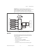

Chapter 3 I/O Connector
© National Instruments Corporation 3-3 NI 6124/6154 User Manual
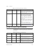
+5 V Power Source
(NI 6124 Only) The +5 V pins on the I/O connector supply +5 V power. You
can use these pins, referenced to D GND, to power external circuitry.
Power rating (most devices): +4.65 to +5.25 VDC at 1 A.
To find your device’s power rating, refer to the specifications document for
your device.
Caution Never connect these +5 V power pins to analog or digital ground or to any other
voltage source on the S Series device or any other device. Doing so can damage the device
and the computer. NI is not liable for damage resulting from such a connection.
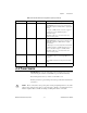
PFI <0..5>/P0.<0..5> D GND Input Programmable Function Interface or Static Digital
Input Channels 0 to 5—Each of these terminals can be
individually configured as a PFI terminal or a digital input
terminal.
As an input, each PFI terminal can be used to supply an
external source for AI or AO timing signals or
counter/timer inputs.
Note: PFI <0..5>/P0.<0..5> are isolated from earth
ground and chassis ground.
PFI <6..9>/P1.<0..3> D GND Output Programmable Function Interface or Static Digital
Output Channels 6 to 9—Each of these terminals can be
individually configured as a PFI terminal or a digital
output terminal.
As a PFI output, you can route many different internal AI
or AO timing signals to each PFI terminal. You also can
route the counter/timer outputs to each PFI terminal.
Note: PFI <6..9>/P1.<0..3> are isolated from earth
ground and chassis ground.
D GND — — Digital Ground—D GND supplies the reference
for input PFI <0..5>/P0.<0..5> and output PFI <6..9>/
P1.<0..3>.
Note: D GND is isolated from earth ground and chassis
ground.
NC — — No Connect—Do not connect signals to these terminals.
Table 3-2. NI 6154 I/O Connector Signal Descriptions (Continued)
I/O Connector Pin Reference Direction Signal Description