USER GUIDE AND SPECIFICATIONS USB-9201/9221 8-Channel, 12-Bit Analog Input Devices This user guide describes how to use the National Instruments USB-9201/9221 devices and lists the specifications. Introduction This user guide describes how to use the National Instruments USB-9201/9221. In this document, the USB-9201/9221 with screw terminal and USB-9201/9221 with DSUB are referred to inclusively as the USB-9201/9221.
Dimensions Figures 2 and 3 show the USB-9201/9221 device dimensions. Hi-Speed USB Carrier NI USB-9162 120.68 mm 118.26 mm 140.23 mm 137.82 mm (4.751 in.) (4.656 in.) (5.521 in.) (5.426 in.) 88.12 mm (3.469 in.) 25.34 mm (0.998 in.) Figure 2. USB-9201/9221 Devices in Inches (Millimeters) Hi-Speed USB Carrier NI USB-9162 125.76 mm 123.38 mm 120.68 mm 118.26 mm (4.951 in.) (4.857 in.) (4.751 in.) (4.656 in.) 88.12 mm (3.469 in.) 25.34 mm (0.998 in.) Figure 3.
Safety Guidelines Operate the USB-9201/9221 only as described in these operating instructions. Although the NI 9201/9221 might have more stringent certification standards than the USB-9201/9221, when used with the USB-9162 carrier, the combined system might be limited. Refer to the Specifications section for more information. Caution Hot Surface This icon denotes that the component may be hot. Touching this component may result in bodily injury.
Software Software support for the USB-9201/9221 is provided by NI-DAQmx. The NI-DAQmx CD contains example programs that you can use to get started programming with the USB-9201/9221. Refer to the NI-DAQmx for USB Devices Getting Started Guide that shipped with your device, and is also accessible from Start»All Programs»National Instruments» NI-DAQ, for more information.
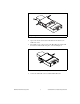
1 1 High Voltage Screw Terminal Backshell Figure 4. Module Installation 4. Squeeze the latches and insert the NI 9201/9221 module into the USB-9162 carrier. 5. Press firmly on the connector side of the NI 9201/9221 module until the latches lock the module into place, as shown in Figure 5. Figure 5. Locking Module into Place 6. © National Instruments Corporation Connect the USB cable to the assembled USB-9201/9221.
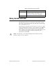
Mounting the USB-9201/9221 to a Panel Threaded inserts are located in the USB-9201/9221 for mounting it to a panel. Refer to Figure 6 for dimensions. 85.7 mm (3.37 in.) 72.2 mm (2.84 in.) Threaded Insert M3 x 0.5 8.5 mm (0.34 in.) Max Depth 76.1 mm (3.00 in.) Figure 6. Module Dimensions Connecting the USB-9201/9221 to a Computer Plug one end of the USB cable into the USB-9201/9221 and the other end into an available USB port on the computer.
Table 1. LED State/Device Status (Continued) LED State Device Status Double-blink Connected to USB full speed port. Device performance might be affected. Refer to the Specifications section for more information. Quadruple-blink Device error. Refer to ni.com/support. Wiring the USB-9201/9221 The USB-9201/9221 provides connections for eight analog input channels. The USB-9201/9221 with screw terminal has a 10-terminal, detachable high voltage screw-terminal backshell.
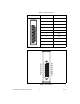
Table 2. Terminal Assignments Module Terminal Signal 0 AI 0 1 AI 1 2 AI 2 3 AI 3 4 AI 4 5 AI 5 6 AI 6 7 AI 7 8 No connection 9 Common (COM) 0 1 2 3 4 5 6 7 8 9 AI0 NC AI1 AI2 NC AI3 AI4 NC AI5 AI6 NC AI7 14 15 16 17 18 19 20 21 22 23 24 25 1 2 3 4 5 6 7 8 9 10 11 12 13 COM NC COM COM NC COM COM NC COM COM NC COM COM Figure 7. Pin Assignments USB-9201/9221 User Guide and Specifications 8 ni.
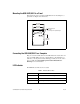
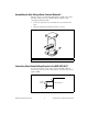
Assembling the High Voltage Screw Terminal Backshell The high voltage screw terminal backshell must be installed when using hazardous voltages (>42.4 Vpk, 60 VDC). Refer to Figure 8 while completing the following steps: 1. Connect the leads to the screw terminal and secure with the strain relief. 2. Finish by snapping the backshell around the connector. 1 1 Strain Relief Figure 8.
Refer to your software documentation, accessible from Start» All Programs»National Instruments»NI-DAQ, for information about different methods of reading USB-9201/9221 data. USB-9201/9221 Circuitry The USB-9201/9221 channels are isolated, and the device protects each channel from overvoltages. The input signals are scanned, buffered, conditioned, and then sampled by a single 12-bit ADC. For more information about overvoltage protection, refer to the Specifications section.
Sample rate (aggregate)1 USB-9201 Single channel.......................... 800 kS/s max Scanning .................................. 500 kS/s USB-9221 ....................................... 800 kS/s max Operating voltage ranges2 USB-9201 ....................................... ±10 V (not software selectable) USB-9221 ....................................... ± 60 V (not software selectable) Maximum voltage, (AI or COM to earth ground, verified by a dielectric withstand test) Screw terminal ...................
Percent of Reading Percent of Range* Uncalibrated typ (25 °C, ±5 °C) ±0.26% ±0.43% Uncalibrated max (0 to 60 °C) ±0.67% ±1.06% Error * Range equals 10.53 V for the USB-9201, 62.50 V for the USB-9221. Stability Offset drift USB-9201.................................±100 μV/°C USB-9221.................................±580 μV/°C Gain drift .........................................±34 ppm/°C Input bandwidth (–3 dB) USB-9201 ........................................690 kHz min USB-9221 ..................
Physical Characteristics If you need to clean the module, wipe it with a dry towel. Dimensions With combicon................................ 14.0 cm × 8.8 cm × 2.5 cm ........................................................ (5.52 in. × 3.47 in. × 1.00 in.) 25-pin DSUB .................................. 12.6 cm × 8.8 cm × 2.5 cm ........................................................ (4.95 in. × 3.47 in. × 1.00 in.) Screw-terminal wiring............................
Isolation Voltages for USB-9201/9221 with DSUB Channel-to-channel.................................None Channel-to-earth ground Continuous.......................................60 VDC, Measurement Category I Withstand.........................................1,000 Vrms, verified by a dielectric withstand test Measurement Category I is for measurements performed on circuits not directly connected to the electrical distribution system referred to as MAINS voltage.
Operating humidity (IEC 60068-2-56) ................................... 10 to 90% RH, noncondensing Storage humidity (IEC 60068-2-56) ................................... 5 to 95% RH, noncondensing Maximum altitude .................................. 2,000 m Pollution Degree (IEC 60664) ............... 2 Electromagnetic Compatibility Emissions ............................................... EN 55011 Class A at 10 m FCC Part 15A above 1 GHz Immunity................................................
Where to Go for Support The National Instruments Web site is your complete resource for technical support. At ni.com/support you have access to everything from troubleshooting and application development self-help resources to email and phone assistance from NI Application Engineers. National Instruments corporate headquarters is located at 11500 North Mopac Expressway, Austin, Texas, 78759-3504. National Instruments also has offices located around the world to help address your support needs.