MXI TM NI ExpressCard MXI Series User Manual ™ NI ExpressCard MXI Multisystem eXtension Interface for ExpressCard , CompactPCI, and PXI Bus (including PXI Express) Systems NI PXI-ExpressCard 8360/NI PXIe-ExpressCard 8360, NI ExpressCard-8360, NI PXI-8360, and NI PXIe-8360 NI ExpressCard MXI Series User Manual August 2008 371575E-01
Support Worldwide Technical Support and Product Information ni.
Important Information Warranty The NI ExpressCard-8360, NI PXI-ExpressCard 8360, NI PXIe-ExpressCard 8360, NI PXI-8360, and NI PXIe-8360 are warranted against defects in materials and workmanship for a period of one year from the date of shipment, as evidenced by receipts or other documentation. National Instruments will, at its option, repair or replace equipment that proves to be defective during the warranty period. This warranty includes parts and labor.
NATIONAL INSTRUMENTS PRODUCTS ARE INCORPORATED IN A SYSTEM OR APPLICATION, INCLUDING, WITHOUT LIMITATION, THE APPROPRIATE DESIGN, PROCESS AND SAFETY LEVEL OF SUCH SYSTEM OR APPLICATION.
Contents About This Manual Conventions ...................................................................................................................vii Related Documentation..................................................................................................viii Chapter 1 Introduction About the NI ExpressCard MXI Series .........................................................................1-1 Description and Features ....................................................................
Contents Appendix B Common Questions Appendix C Technical Support and Professional Services Glossary Index NI ExpressCard MXI Series User Manual vi ni.
About This Manual This manual describes the features, functions, and operation of the NI ExpressCard MXI series of products. The products in this series are the NI PXI-ExpressCard 8360, NI PXIe-ExpressCard 8360, NI ExpressCard-8360, NI PXI-8360, and the NI PXIe-8360. Conventions The following conventions appear in this manual: » The » symbol leads you through nested menu items and dialog box options to a final action.
About This Manual NI ExpressCard MXI board NI ExpressCard MXI board refers to either of the following boards, unless otherwise noted: NI ExpressCard-8360 and NI PXI-8360. PXIe The term PXIe refers to PXI Express. In this manual, whenever a PXI chassis is referenced, a CompactPCI chassis could be used instead.
1 Introduction This chapter describes the NI ExpressCard MXI series of products, lists what you need to get started, and explains how to unpack and set up your hardware. The products in this series are the NI ExpressCard-8360, NI PXIe-8360, and NI PXI-8360. For the remainder of this manual, the term NI ExpressCard MXI board refers to any product in the NI ExpressCard MXI series. NI ExpressCard MXI boards must always be installed as an ExpressCard board and a PXI board.
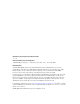
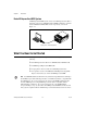
Chapter 1 Introduction Basic NI ExpressCard MXI System An NI ExpressCard MXI system consists of an NI ExpressCard-8360 in a laptop PC connected to an NI PXI-8360 or NI PXIe-8360 in the controller slot of a PXI/cPCI or PXIe/cPCIe chassis respectively, as shown in Figure 1-1. Laptop PC to PXI/CompactPCI Figure 1-1.
Chapter 1 Introduction Some laptops do not expect bridges behind an ExpressCard module, and they will not configure the PXI/cPCI system correctly. Refer to the Related Links section of KnowledgeBase 3U7CI4D8 for a link to a list of compatible laptops. Note Unpacking Your NI ExpressCard MXI boards are shipped in antistatic packages to prevent electrostatic damage (ESD) to the devices. ESD can damage several components on the device. Caution Never touch the exposed pins of connectors.
Hardware Installation 2 This chapter explains how to install the NI ExpressCard MXI hardware. Hardware Installation The following are general instructions for installing the NI ExpressCard MXI boards. Consult your computer user manual or technical reference manual for specific instructions and warnings.
Chapter 2 Hardware Installation 4. Make sure the injector/ejector handle is in its downward position. Be sure to remove all connector packaging and protective caps from retaining screws on the module. Align the NI PXI-8360 or NI PXIe-8360 with the card guides on the top and bottom of the system controller slot. Caution Do not raise the injector/ejector handle as you insert the NI PXI-8360 or NI PXIe-8360.
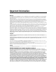
Chapter 2 Hardware Installation Figure 2-2 shows an NI PXI-8360 or NI PXIe-8360 just before installation in the system controller slot of a National Instruments chassis. 2 NI PX I-1 04 1 2 3 4 1 2 NI PXI-8360 or NI PXIe-8360 PXI/cPCI or PXI Express/CompactPCI Express Chassis 3 4 PXI/cPCI or PXIe/cPCIe Slot 1 Ejector Handle in Down Position Figure 2-1.
Chapter 2 Hardware Installation If your computer is already running (or hibernating, etc.) when you install NI ExpressCard MXI, you must reboot to detect the PXI system. Otherwise, the PXI system is detected when you start your computer. Figure 2-2 shows how to insert the NI ExpressCard-8360 and connect the cable. 3 2 1 1 MXI-Express Cable 2 ExpressCard Slot 3 Portable Computer Figure 2-2.
Chapter 2 Hardware Installation Notes For more information about cables, refer to the NI ExpressCard MXI Cable Options section of Chapter 3, Hardware Overview. You cannot use two NI PXI-8360 or NI PXIe-8360 boards for chassis expansion as with MXI-4. You can connect only an NI PCIe-8361/8362 or an NI ExpressCard-8360 host device to an NI PXI-8360 or NI PXIe-8360. Powering Up the NI ExpressCard MXI System To power up the NI ExpressCard MXI system, follow these steps: 1. Power on the expansion chassis.
3 Hardware Overview This chapter presents an overview of NI ExpressCard MXI hardware functionality and explains the operation of each functional unit. Functional Overview NI ExpressCard MXI is based on PCI Express technology. An NI ExpressCard MXI kit uses standard PCI Express bridges or switches. The architecture is transparent to device drivers, so no additional software is needed to support NI ExpressCard MXI. No software is required for basic functionality. SMBus and ID device both require drivers.
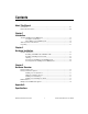
Hardware Overview PCI EXPRESS NI ExpressCard-8360 PCI Express Cable Driver PXI-8360 High-Speed Cable Connector High-Speed Cable Connector PCI Express to PCI Bridge PXI BUS Chapter 3 High-Speed Cable Connector High-Speed Cable Connector PCI Express Switch PCIe Links PCI Express Cable Driver PXIe-8360 PCI Slots PCI EXPRESS NI ExpressCard-8360 SMBus Figure 3-1. NI ExpressCard MXI Block Diagram with NI PXI-8360 Figure 3-2.
Chapter 3 Hardware Overview Functional Unit Descriptions PCI Express x1 Cable Driver This PCI Express device consists of one upstream and one downstream PCI Express physical interface. It buffers the PCI Express signals and drives them onto the cable. High-Speed Cable Connector The high-speed cable connector provides all necessary signals to connect an NI ExpressCard-8360 and an NI PXI-8360 or NI PXIe-8360.
Chapter 3 Hardware Overview Table 3-1 provides the status descriptions for the LEDs on the NI PXI-8360 and NI PXIe-8360. Table 3-1. LED Status Descriptions for NI PXI-8360 and NI PXIe-8360 LED Color PWR Off No power Red Power is out of spec Green Power is within spec Off Link not established LINK Green Meaning Link established The NI PXIe-8360 has some additional LEDs on the back side of the board near the front-panel connector.
A Specifications This appendix lists the system specifications for NI ExpressCard-8360, NI PXI-8360, and NI PXIe8360 boards. NI PXI-8360 Physical NI PXI-8360 Dimensions............................................. 10.0 × 16.0 cm (3.9 × 6.3 in.) Maximum cable length........................... 7 m Slot requirements ................................... One controller slot Compatibility ......................................... Fully compatible with the PXI Hardware Specification, Revision 2.1 Weight ........
Appendix A Specifications Environment1 Maximum altitude...................................2,000 m (at 25 °C ambient temperature) Pollution Degree .....................................2 Indoor use only Operating Environment Ambient temperature range ....................0 to 55 °C (Tested in accordance with IEC-60068-2-1 and IEC-60068-2-2.) Relative humidity range..........................10 to 90%, noncondensing (Tested in accordance with IEC-60068-2-56.) Storage Environment Ambient temperature range ...
Appendix A Specifications Random Vibration Operating ........................................ 5 to 500 Hz, 0.3 grms Nonoperating .................................. 5 to 500 Hz, 2.4 grms (Tested in accordance with IEC-60068-2-64. Nonoperating test profile exceeds the requirements of MIL-PRF-28800F, Class 3.) NI PXIe-8360 Physical NI PXIe-8360 Dimensions............................................. 10.0 × 16.0 cm (3.9 × 6.3 in.) Maximum cable length........................... 7 m Slot requirements ........
Appendix A Specifications Environment1 Maximum altitude...................................2,000 m (800 mbars) (at 25 °C ambient temperature) Pollution Degree .....................................2 Indoor use only Operating Environment Ambient temperature range ....................0 to 55 °C (Tested in accordance with IEC-60068-2-1 and IEC-60068-2-2. Meets MIL-PRF-28800F Class 3 low temperature limit and MIL-PRF-28800F Class 2 high temperature limit.) Relative humidity range..........................
Appendix A Specifications Random Vibration Operating................. 5 to 500 Hz, 0.3 grms Nonoperating .................................. 5 to 500 Hz, 2.4 grms (Tested in accordance with IEC-60068-2-64. Nonoperating test profile exceeds the requirements of MIL-PRF-28800F, Class 3.) NI ExpressCard-8360 Physical Dimensions............................................. 10.2 × 3.4 cm (4.0 × 1.3 in.) Maximum cable length........................... 7 m Slot requirements ...................................
Appendix A Specifications Operating Environment Module ambient temperature range ........0 to 65 °C (Tested in accordance with IEC-60068-2-1 and IEC-60068-2-2.) Operating relative humidity....................5 to 95%, noncondensing (Tested in accordance with IEC-60068-2-56.) Storage Environment Ambient temperature range ....................–20 to 65 °C (Tested in accordance with IEC-60068-2-1 and IEC-60068-2-2.) Nonoperating thermal shock...................
Appendix A Specifications Common Specs Safety This product is designed to meet the requirements of the following standards of safety for electrical equipment for measurement, control, and laboratory use: • IEC 61010-1, EN 61010-1 • UL 61010-1, CSA 61010-1 Note For UL and other safety certifications, refer to the product label, or visit ni.com/ certification, search by model number or product line, and click the appropriate link in the Certification column.
Appendix A Specifications Environmental Management National Instruments is committed to designing and manufacturing products in an environmentally responsible manner. NI recognizes that eliminating certain hazardous substances from our products is beneficial not only to the environment but also to NI customers. For additional environmental information, refer to the NI and the Environment Web page at ni.com/environment.
B Common Questions This appendix lists common questions related to the use of the NI ExpressCard MXI controllers. General Hardware What are the board names of the NI ExpressCard MXI remote controllers? • NI ExpressCard-8360: ExpressCard MXI Interface • NI PXI-8360: MXI Express Interface • NI PXIe-8360: MXI Express for PXI Express Interface Is NI ExpressCard MXI compatible with NI MXI Express? NI ExpressCard MXI and NI MXI Express use the same cable and PXI/cPCI module (the NI PXI-8360).
Appendix B Common Questions General Cabling What is the maximum length of an NI ExpressCard MXI copper cable? The maximum length for an NI ExpressCard MXI copper cable is 7 m. National Instruments offers 1 m, 3 m, and 7 m copper cables. General Software Under which operating systems will NI ExpressCard MXI work? NI ExpressCard MXI is a PCI-to-PCI bridge that is recognized by the majority of operating systems.
Appendix B Common Questions How does my NI ExpressCard MXI board show up in the Windows Device Manager? NI ExpressCard MXI boards contain two types of PCI devices onboard and will have several listings in the Windows Device Manager (WDM). The first devices show up in the WDM listed under System devices as PCI standard PCI-to-PCI bridges. The second device type shows up in the WDM as an NI PXI-8360 or NI PXIe-8360 SMBus Controller when the correct NI ExpressCard MXI driver is installed.
Appendix B Common Questions Can I use a MXI-3, MXI-4, and NI ExpressCard MXI kit in the same multichassis PXI system? Yes. Different MXI kits can be intermixed to connect multiple PXI chassis together. As mentioned previously, an individual MXI-3 or MXI-4 board will not cable directly to an NI ExpressCard MXI board. MXI-3 and MXI-4 systems required the use of a specific boot ordering. Is this a requirement with NI ExpressCard MXI? Yes.
Technical Support and Professional Services C Visit the following sections of the award-winning National Instruments Web site at ni.com for technical support and professional services: • Support—Technical support resources at ni.com/support include the following: – Self-Help Technical Resources—For answers and solutions, visit ni.
Appendix C Technical Support and Professional Services • Declaration of Conformity (DoC)—A DoC is our claim of compliance with the Council of the European Communities using the manufacturer’s declaration of conformity. This system affords the user protection for electromagnetic compatibility (EMC) and product safety. You can obtain the DoC for your product by visiting ni.com/certification.
Glossary Symbol Prefix Value n nano 10 –9 μ micro 10 – 6 m milli 10 –3 k kilo 10 3 M mega 10 6 Symbols ° Degrees ≥ Equal or greater than ≤ Equal or less than % Percent B bus The group of conductors that interconnect individual circuitry in a computer. Typically, a bus is the expansion vehicle to which I/O or other devices are connected. Examples of PC buses are the AT bus, NuBus, Micro Channel, and EISA bus.
Glossary D device A plug-in instrument board or pad that can contain multiple channels and conversion devices. Plug-in boards and PCMCIA cards, which connect to your computer parallel port, are examples of devices. digital trigger A TTL level signal having two discrete levels—a high and a low level. DMA Direct Memory Access—a method by which data can be transferred to/from computer memory from/to a device or memory on the bus while the processor does something else.
Glossary X x1 A link or port with one physical lane.
Index B basic NI ExpressCard MXI configuration (figure), 1-2 basic NI ExpressCard MXI system, 1-2 block diagram with NI PXI-8360 (figure), 3-2 block diagram with NI PXIe-8360 (figure), 3-2 environmental management specifications, A-8 environmental specifications NI ExpressCard-8360, A-5 NI PXI-8360, A-2 NI PXIe-8360, A-4 examples (NI resources), C-1 C F cable options (table), 3-4 cabling common questions, B-2 calibration certificate (NI resources), C-2 CE compliance specifications, A-7 cleaning NI PXI-8
Index L overview functional, 3-1 functional unit descriptions, 3-3 hardware, 3-1 LED indicators, 3-3 M MXI-3 to NI ExpressCard MXI common questions, B-3 P PCI Express x1 cable driver, 3-3 PCI Express-to-PCI bridge, 3-3 PCI Express-to-PCI Express switch, 3-3 physical specifications NI ExpressCard-8360, A-5 NI PXI-8360, A-1 NI PXIe-8360, A-3 programming examples (NI resources), C-1 N National Instruments support and services, C-1 NI ExpressCard MXI basic system, 1-2 block diagram with NI PXI-8360 (figur
Index T NI PXI-8360/NI PXIe-8360 cleaning, A-6 electromagnetic compatibility, A-7 safety, A-7 NI PXIe-8360, A-3 environmental, A-4 physical, A-3 waste electrical and electronic equipment, A-8 storage environment specifications NI ExpressCard-8360, A-6 NI PXI-8360, A-2 NI PXIe-8360, A-4 support, technical, C-1 © National Instruments Corporation technical support, C-1 training and certification (NI resources), C-1 troubleshooting (NI resources), C-1 U unpacking, 1-3 W waste electrical and electronic equ