NI Vision NI PCI-1410 User Manual High-Quality Monochrome Image Acquisition Device NI PCI-1410 User Manual February 2007 373793C-01
Support Worldwide Technical Support and Product Information ni.
Important Information Warranty The NI PCI-1410 is warranted against defects in materials and workmanship for a period of one year from the date of shipment, as evidenced by receipts or other documentation. National Instruments will, at its option, repair or replace equipment that proves to be defective during the warranty period. This warranty includes parts and labor.
Compliance Compliance with FCC/Canada Radio Frequency Interference Regulations Determining FCC Class The Federal Communications Commission (FCC) has rules to protect wireless communications from interference. The FCC places digital electronics into two classes. These classes are known as Class A (for use in industrial-commercial locations only) or Class B (for use in residential or commercial locations). All National Instruments (NI) products are FCC Class A products.
Conventions The following conventions are used in this manual: <> Angle brackets that contain numbers separated by an ellipsis represent a range of values associated with a bit or signal name—for example, AO <3..0>. » The » symbol leads you through nested menu items and dialog box options to a final action. The sequence File»Page Setup»Options directs you to pull down the File menu, select the Page Setup item, and select Options from the last dialog box.
Contents Chapter 1 Introduction About the NI 1410 Device .............................................................................................1-1 Software Overview ........................................................................................................1-2 NI-IMAQ Driver Software ..............................................................................1-3 National Instruments Application Software ....................................................
Contents Appendix A Custom Cables Appendix B Technical Support and Professional Services Glossary Index NI PCI-1410 User Manual viii ni.
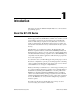
1 Introduction This chapter describes the NI PCI-1410 (NI 1410) device and its software programming options. About the NI 1410 Device The NI 1410 is a high-accuracy, monochrome image acquisition device for PCI that supports RS-170, CCIR, NTSC, and PAL video standards, as well as nonstandard cameras from any of four input sources. The NI 1410 features a 10-bit analog-to-digital converter (ADC) that converts video signals to digital formats.
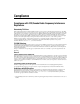
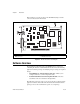
Chapter 1 Introduction Refer to Figure 1-1 for the location of the NI 1410 W1 jumper and the connectors discussed in this manual. NATIONAL INSTRUMENTS 4 3 © COPYRIGHT 2004 2 1 2 NI PCI-1410 1 68-Pin VHDCI Connector BNC Connector 3 4 W1 Jumper RTSI Bus Connector Figure 1-1. NI PCI-1410 Parts Locator Diagram Software Overview Programming the NI 1410 requires the NI-IMAQ driver software for controlling the hardware.
Chapter 1 Introduction NI-IMAQ Driver Software The NI 1410 ships with NI Vision Acquisition Software, which includes the NI-IMAQ driver software. NI-IMAQ has an extensive library of functions—such as routines for video configuration, continuous and single shot image acquisition, memory buffer allocation, trigger control, and device configuration—you can call from the application development environment (ADE).
Chapter 1 Introduction individual tasks. You also can migrate the configured inspection to LabVIEW, extending the capabilities of the applications if necessary.
Chapter 1 Introduction Integration with DAQ and Motion Control Platforms that support NI-IMAQ also support NI-DAQ and a variety of National Instruments DAQ devices. This allows integration between image acquisition devices and National Instruments DAQ products.
2 Hardware Overview This chapter describes the features of the NI PCI-1410 device and includes information about acquisition modes, analog front-end considerations, and clamping. Functional Overview The NI 1410 features a flexible, high-speed data path optimized for the acquisition and formatting of video data from analog cameras. The NI 1410 can acquire from RS-170/NTSC, CCIR/PAL, VGA, and progressive scan cameras, as well as from non-standard cameras such as line scan cameras.
Chapter 2 Hardware Overview The block diagram in Figure 2-1 illustrates the key functional units of the NI 1410.
Chapter 2 Hardware Overview Digital Filter and LUT The digital filter removes chrominance from a composite color video signal that conforms to either PAL or NTSC. The output of the digital filter passes through the 1,024 × 10-bit lookup table (LUT). You can configure the LUT to implement simple imaging operations such as contrast enhancement, data inversion, gamma correction, or other user-defined transfer functions.
Chapter 2 Hardware Overview Acquisition and Region-of-Interest Control The acquisition and region-of-interest (ROI) control circuitry routes the active pixels from the 10-bit ADC to the onboard memory. The NI 1410 can perform ROI and scaling on all video lines. Pixel and line scaling transfers certain multiples (two, four, or eight) of pixels and lines to onboard memory.
Chapter 2 • Hardware Overview External HSYNC/VSYNC (HLOCK only) Mode—In external HSYNC/VSYNC (HLOCK only) mode, the NI 1410 receives the external HSYNC and VSYNC signals and internally generates the PCLK signal. In this mode, the NI 1410 genlock circuitry uses only the HSYNC signal for locking. You can use this mode to acquire from asynchronously reset cameras that output a continuous HSYNC.
Chapter 2 Hardware Overview To prevent this problem, open Measurement & Automation Explorer (MAX) and navigate to the Advanced tab of the camera file property page. Use the following guidelines to adjust the Clamp Start and Clamp Stop values until the image is corrected: NI PCI-1410 User Manual • Minimum Clamp Start is 100 • Maximum Clamp Stop is 120 • Difference between Clamp Start and Clamp Stop is at least 10 2-6 ni.
3 Signal Connections This chapter describes cable connections for the NI PCI-1410 device. Video Input Channels The video input channels for the NI 1410 support two input modes—referenced single-ended (RSE) and differential (DIFF). A channel configured in DIFF mode uses two inputs. One input connects to the positive terminal, and the other connects to the negative terminal. A channel configured in RSE mode uses one input, which connects to the positive terminal.
Chapter 3 Signal Connections NATIONAL INSTRUMENTS 4 3 © COPYRIGHT 2004 2 NI PCI-1410 1 1 68-Pin VHDCI Connector 3 W1 Jumper 2 BNC Connector 4 RTSI Bus Connector Figure 3-1. NI PCI-1410 Parts Locator Diagram Figure 3-2 shows the BNC connector pin assignments. GND VIDEO0+ Figure 3-2.
Chapter 3 Signal Connections Figure 3-3 shows the pinout of the 68-pin VHDCI connector.
Chapter 3 Signal Connections Digital I/O Connector Signal Connection Descriptions Table 3-1 describes each signal connection on the 68-pin VHDCI connector. Table 3-1. I/O Connector Signals Signal Name Description VIDEO0± VIDEO0± allows for a DIFF or RSE connection. To operate in RSE mode, you must connect VIDEO0– to DGND. When you use VIDEO0+ or VIDEO0–, you must disconnect the video signal from the BNC connector. To operate in DIFF mode, remove attached W1 jumper. VIDEO<3..1>± VIDEO<3..
Chapter 3 Signal Connections Table 3-1. I/O Connector Signals (Continued) Signal Name Description TRIG<3..0> Triggers<3..0> are TTL I/O lines used to start or stop an acquisition or output an acquisition status. You can program the triggers to be rising- or falling-edge sensitive. You also can program the triggers to be programmatically asserted or unasserted, which is similar in function to a digital I/O line, or to contain specific pulse widths or internal status signals by using the onboard events.
A Custom Cables This appendix lists specifications for building custom cables to use with the NI PCI-1410 device. Cable Specification National Instruments offers cables and accessories for you to connect to video sources, trigger sources, or synchronization sources. Use the following guidelines when developing your own cables: • For the video inputs, use a 75 Ω shielded coaxial cable. • For the digital triggers and synchronization signals, use twisted pairs for each signal.
Technical Support and Professional Services B Visit the following sections of the National Instruments Web site at ni.com for technical support and professional services: • Support—Online technical support resources at ni.
Appendix B Technical Support and Professional Services • Calibration Certificate—If your product supports calibration, you can obtain the calibration certificate for your product at ni.com/calibration. If you searched ni.com and could not find the answers you need, contact your local office or NI corporate headquarters. Phone numbers for our worldwide offices are listed at the front of this manual. You also can visit the Worldwide Offices section of ni.
Glossary A A/D Analog-to-digital. ADC Analog-to-digital converter. An electronic device, often an integrated circuit, that converts an analog voltage to a digital value. address Value that identifies a specific location (or series of locations) in memory. antichrominance filter Removes the color information from the video signal. ASIC Application-Specific Integrated Circuit.
Glossary D DAQ Data acquisition. (1) Collecting and measuring electrical signals from sensors, transducers, and test probes or fixtures and inputting them to a computer for processing. (2) Collecting and measuring the same kinds of electrical signals with A/D or DIO boards plugged into a computer, and possibly generating control signals with D/A and/or DIO boards in the same computer. DMA Direct memory access.
Glossary H HSYNC Horizontal synchronization signal. The synchronization pulse signal produced at the beginning of each video scan line that keeps a video monitor’s horizontal scan rate in step with the transmission of each new line. I instrument driver A set of high-level software functions, such as NI-IMAQ, that control specific plug-in computer boards.
Glossary N NI-IMAQ Driver software for National Instruments image acquisition hardware. NTSC National Television Standards Committee. The committee that developed the color video standard used primarily in North America, which uses 525 lines per frame. See also PAL. P PAL Phase Alternation Line. One of the European video color standards. PAL uses 625 lines per frame. See also NTSC. PCI Peripheral Component Interconnect.
Glossary RSE Referenced single-ended. All measurements are made with respect to a common reference measurement system or a ground. Also called a grounded measurement system. RTSI bus Real-Time System Integration Bus. The National Instruments timing bus that connects image acquisition and DAQ boards directly by means of connectors on top of the boards for precise synchronization of functions. S scatter-gather DMA A type of DMA that allows the DMA controller to reconfigure on-the-fly.
Index Numerics CTRL<3..
Index N functional overview, 2-1 genlock and synchronization circuitry, 2-3 PCI Interface, 2-3 PCLK, HSYNC, VSYNC mux, 2-3 programmable gain and offset, 2-2 RTSI bus, 2-4 scatter-gather DMA controllers, 2-3 video mux, 2-2 help, technical support, B-1 HSYNC genlock and synchronization circuitry, 2-3 PCLK, HSYNC, VSYNC mux, 2-3 HSYNCIN± signal (table), 3-4 National Instruments support and services, B-1 NI support and services, B-1 NI-IMAQ driver software, 1-3 P parts locator diagram, 1-2, 3-2 PCI interfac
Index S V scatter-gather DMA controllers, 2-3 signal connections BNC connector, 3-1 I/O connector, 3-2 pin assignments (figure), 3-3 signal descriptions (table), 3-4 software NI resources, B-1 Vision Development Module, 1-4 software programming choices NI Vision, 1-3 NI-IMAQ driver software, 1-3 standard acquisition mode, 2-4 support, technical, B-1 SYNC mux, 2-3 synchronization circuitry, 2-3 vertical synchronization. See VSYNC VHDCI connector. See I/O connector video mux, 2-2 VIDEO<3..