SCXI TM SCXI-1503 User Manual March 2007 374271A-01
Support Worldwide Technical Support and Product Information ni.
Important Information Warranty The SCXI-1503 is warranted against defects in materials and workmanship for a period of one year from the date of shipment, as evidenced by receipts or other documentation. National Instruments will, at its option, repair or replace equipment that proves to be defective during the warranty period. This warranty includes parts and labor.
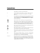
Conventions The following conventions are used in this manual: <> Angle brackets that contain numbers separated by an ellipsis represent a range of values associated with a bit or signal name—for example, P0.<3..0>. » The » symbol leads you through nested menu items and dialog box options to a final action. The sequence File»Page Setup»Options directs you to pull down the File menu, select the Page Setup item, and select Options from the last dialog box.
Contents Chapter 1 About the SCXI-1503 What You Need to Get Started ......................................................................................1-1 National Instruments Documentation ............................................................................1-2 Installing Application Software, NI-DAQ, and the E/M Series DAQ Device ..............1-4 Installing the SCXI-1503 Module into the SCXI Chassis...............................1-4 Installing the Terminal Block.................................
Contents Chapter 4 Theory of Operation Rear Signal Connector, SCXIbus Connector, and SCXIbus Interface.......................... 4-3 Digital Control Circuitry ............................................................................................... 4-3 Analog Circuitry............................................................................................................ 4-3 Analog Input Channels....................................................................................
Contents Appendix A Specifications Appendix B Removing the SCXI-1503 Appendix C Common Questions Glossary Index Figures Figure 2-1. Figure 2-2. Figure 2-3. Figure 2-4. 4-Wire Resistive Sensor Connected in a 4-Wire Configuration ...........2-3 2-Wire Resistive Sensor Connected in a 2-Wire Configuration ...........2-4 3-Wire Resistive Sensor Configuration.................................................2-5 3-Wire Configuration Using Matched Current Sources........................2-6 Figure 4-1. Figure 4-2.
Contents Tables Table 1-1. Supported SCXI-1503 Terminal Blocks ............................................... 1-4 Table 2-1. Table 2-2. Table 2-3. Table 2-4. Front Signal Pin Assignments .............................................................. 2-8 Signal Descriptions ............................................................................... 2-9 Rear Signal Pin Assignments................................................................ 2-10 SCXI-1503 50-Pin Rear Connector Signals ............
1 About the SCXI-1503 This manual describes the electrical and mechanical aspects of the SCXI-1503 module and contains information concerning its installation and operation. The SCXI-1503 module provides 16 differential input channels and 16 channels of 100 μA current excitation and one cold junction sensor channel. The SCXI-1503 is ideally suited for measuring resistive transducers, such as RTDs or thermistors.
Chapter 1 About the SCXI-1503 – One of the following: • SCXI-1600 • E/M Series DAQ device – Computer – Cabling, cable adapter, and sensors as required for your application ❑ Software – NI-DAQ 8.
Chapter 1 About the SCXI-1503 • SCXI or PXI/SCXI chassis manual—Read this manual for maintenance information on the chassis and for installation instructions. • The DAQ Getting Started Guide—This document has information on installing NI-DAQ and the E/M Series DAQ device. Install these before you install the SCXI module. • The SCXI hardware user manuals—Read these manuals for detailed information about signal connections and module configuration.
Chapter 1 About the SCXI-1503 Installing Application Software, NI-DAQ, and the E/M Series DAQ Device Refer to the DAQ Getting Started Guide packaged with the NI-DAQ software to install your application software, NI-DAQ driver software, and the DAQ device to which you will connect the SCXI-1503. NI-DAQ 8.1 or later is required to configure and program the SCXI-1503 module. If you do not have NI-DAQ 8.
Chapter 1 About the SCXI-1503 Verifying the SCXI-1503 Installation Refer to the SCXI Quick Start Guide, for details about testing the SCXI chassis and module installation in software. Refer to Chapter 3, Configuring and Testing, for details about setting up a task and verifying the input signal.
2 Connecting Signals This chapter describes the input and output signal connections to the SCXI-1503 module with the module front connector and rear signal connector. This chapter also includes connection instructions for the signals on the SCXI-1503 module when using the SCXI-1306 terminal block. In addition to this section, refer to the installation guide of the terminal block for detailed information regarding connecting the signals.
Chapter 2 Connecting Signals Note Exceeding the differential or common-mode input channel ranges results in a distorted signal measurement, and can also increase the settling time requirement of the connected E/M Series DAQ device. Ground-Referencing the Signals Do not ground signals that are already ground-referenced; doing so results in a ground loop, which can adversely affect the measurement accuracy.
Chapter 2 Connecting Signals 4-Wire Configuration The 4-wire configuration, also referred to as a Kelvin connection, is shown in Figure 2-1. The 4-wire configuration uses one pair of wires to deliver the excitation current to the resistive sensor and uses a separate pair of wires to sense the voltage across the resistive sensor. Because of the high input impedance of the differential amplifier, negligible current flows through the sense wires.
Chapter 2 Connecting Signals 2-Wire Configuration The basic 2-wire configuration is shown in Figure 2-2. In this configuration an error voltage (VE) is introduced into the measurement equal to the excitation current (IEX) times the sum of the two lead resistances, RL1 and RL2.
Chapter 2 Connecting Signals 3-Wire Resistive Sensor Configuration If you are using a 3-wire resistive sensor, you can reduce the error voltage by one-half over the 2-wire measurement by connecting the device as shown in Figure 2-3. In this configuration, very little current flows through RL3 and therefore RL2 is the only lead resistance that introduces an error into the measurement.
Chapter 2 Connecting Signals Lead-Resistance Compensation Using a 3-Wire Resistive Sensor and Two Matched Current Sources You can compensate for the errors introduced by lead-resistance voltage drops by using a 3-wire resistive sensor and two matched current sources connected as shown in Figure 2-4. External Sensor SCXI-1306 RL1 SCXI-1503 EX0+ AI0+ AI0– + – I = 100 µA + – I = 100 µA EX0– RT ON RL2 RL3 EX1+ AI1+ AI1– EX1– ON Figure 2-4.
Chapter 2 Connecting Signals In this configuration, the lead-resistance voltage drop across RL3 is converted into a common-mode voltage that is rejected by the differential amplifier. Also, the polarity of the lead-resistance voltage drops across RL1 and RL2 are series opposing, relative to the inputs of the differential amplifier, eliminating their effect on the voltage measured across RT. Note RL1 and RL2 are assumed to be equal.
Chapter 2 Connecting Signals Table 2-1.
Chapter 2 Connecting Signals Table 2-2. Signal Descriptions Pin Signal Name Description A1 +5 V +5 VDC Source—Used to power circuitry on the terminal block. 0.1 mA of source not protected. A13 – A16, A29 – A32 GND Ground—Tied to the SCXI module ground. A1, A19, A20, A25 – A28 RSVD Reserved—This pin is reserved. Do not connect any signal to this pin. A2 C GND Chassis Ground—Connects to the SCXI chassis. B24 – B17, B8 – B1 IEX<0..7> –, IEX<8..
Chapter 2 Connecting Signals Rear Signal Connector Table 2-3 shows the SCXI-1503 module rear signal connector pin assignments. Table 2-3.
Chapter 2 Connecting Signals Rear Signal Connector Descriptions The rear signal connector on the cabled module is the interface between the DAQ device and all modules in the SCXI chassis. AI 0 is used to differentially multiplex all 16 channels, the CJ sensor, and analog signals from the modules to the connected DAQ device. The communication signals between the DAQ device and the SCXI system are listed in Table 2-4.
Chapter 2 Connecting Signals Table 2-4. SCXI-1503 50-Pin Rear Connector Signals (Continued) Pin SCXI Signal Name NI-DAQmx Device Signal Name Direction Description 26 SER DAT OU T P0.4 Output Serial data out—this signal taps into the SCXIbus MISO line to accept serial output data from a module. 27 DAQ D*/A P0.1 Input Board data/address line—this signal taps into the SCXIbus D*/A line to indicate to the module whether the incoming serial stream is data or address information.
Configuring and Testing 3 This chapter discusses configuring the SCXI-1503 in MAX using NI-DAQmx, creating and testing a virtual channel, global channel, and/or task. Notes You must have NI-DAQmx 8.1 or later installed. Refer to the SCXI Quick Start Guide if you have not already configured the chassis. SCXI-1503 Software-Configurable Settings This section describes how to set the gain/input signal range and how to configure your software for compatible sensor types.
Chapter 3 Configuring and Testing Input Coupling The front end of the SCXI-1503 includes a software configurable switch that allows you to programmatically connect the input channels of the SCXI-1503 to either the front connector or internal ground. When using autozero, the coupling mode is set automatically. Refer to Table 5-1, NI-DAQmx Voltage Measurement Properties, for details about the available input coupling modes supported by the SCXI-1503.
Chapter 3 Configuring and Testing NI-DAQmx Using NI-DAQmx, you can configure software settings such as sensor type and gain/input signal range in the following ways: • Task or global channel in MAX • Functions in your application All software-configurable settings are not configurable both ways. This section only discusses settings in MAX. Refer to Chapter 5, Using the SCXI-1503, for information on using functions in your application.
Chapter 3 Configuring and Testing selecting channels. If you are creating a channel, you can only select one channel. Click Next. 7. Name the task or channel and click Finish. 8. Select the channel(s) you want to configure. You can select a range of channels by holding down the key while selecting the channels. You can select multiple individual channels by holding down the key while selecting channels.
Chapter 3 Configuring and Testing 6. Click the Test button. 7. Click the Start button. 8. After you have completed verifying the channels, click the Stop button. You have now verified the SCXI-1503 configuration and signal connection. For more information on how to further configure the SCXI-1503, or how to use LabVIEW to configure the module and take measurements, refer to Chapter 5, Using the SCXI-1503.
4 Theory of Operation This chapter provides a brief overview and a detailed discussion of the circuit features of the SCXI-1503 module. Refer to Figure 4-1 while reading this section.
SCXI-1503 User Manual 4-2 Input Protection and Lowpass Filter Gain 31 CJSENSOR Lowpass Filter Lowpass Filter Buffer Buffer Buffer Buffer Digital Interface and Control Switch Calibration EEPROM Gain Select Input Select Mux IEX 15 – 100 µA 100 µA – Inst. Amp + – Inst.
Chapter 4 Theory of Operation The major components of the SCXI-1503 modules are as follows: • Rear signal connector • SCXIbus connector • SCXIbus interface • Digital control circuitry • Analog circuitry The SCXI-1503 modules consist of 16 multiplexed input channels, each with a software-programmable gain of 1 or 100. Each input channel has its own lowpass filter. Each channel has a fixed 100 μA current excitation.
Chapter 4 Theory of Operation The CJ SENSOR input channel is used to read the sensor temperature from the terminal block. The temperature sensor is for cold-junction compensation of thermocouple measurements. The CJ SENSOR channel also passes through a 5 Hz lowpass filter to reject unwanted noise on the SCXI-1503. Along with the other 16 input channels, the CJ SENSOR is multiplexed to the output buffer, where it can be read by the DAQ device.
Chapter 4 Theory of Operation The module includes first-in first-out (FIFO) memory for storing the channel scan list defined in your application code. NI-DAQ drivers load the FIFO based on the channel assignments you make in your application. You need not explicitly program the module FIFO as this is done automatically for you by the NI-DAQ driver.
Chapter 4 Theory of Operation changes in resistance, you must use special configurations that minimize measured errors caused by lead-wire resistance. RTD Measurement Errors Because the RTD is a resistive device, you must pass a current through the device and monitor the resulting voltage. However, any resistance in the lead wires that connect the measurement system to the RTD adds error to the readings.
Chapter 4 Theory of Operation defined as the change in RTD resistance from 0 to 100 °C, divided by the resistance at 0 °C, divided by 100 °C: R 100 – R 0 α(Ω/Ω/°C) = ----------------------------R 0 × 100 °C where R100 is the resistance of the RTD at 100 °C. R0 is the resistance of the RTD at 0 °C. For example, a 100 Ω platinum RTD with α = 0.003911 has a resistance of 139.11 Ω at 100 °C. Figure 4-3 displays a typical resistance-temperature curve for a 100 Ω platinum RTD.
Chapter 4 Theory of Operation Although the resistance-temperature curve is relatively linear, accurately converting measured resistance to temperature requires curve fitting. The following Callendar-Van Dusen equation is commonly used to approximate the RTD curve: 2 3 R T = R 0 [ 1 + AT + BT + C ( T – 100 ) ] where RT is the resistance of the RTD at temperature T. R0 is the resistance of the RTD at 0 °C. A, B, and C are the Callendar-Van Dusen coefficients shown in Table 4-1. T is the temperature in °C.
Chapter 4 Theory of Operation Table 4-1. Platinum RTD Types (Continued) Standard Temperature Coefficient of Resistance (TCR, PPM) Typical R0 3911 100 Ω US Industrial Standard American Callendar-Van Dusen Coefficient A = 3.9692 × 10⁻³ B = –5.8495 × 10⁻⁷ C = –4.233 × 10⁻¹² ITS-90 3928 100 Ω A = 3.9888 × 10⁻³ B = –5.915 × 10⁻⁷ C = –3.85 × 10⁻¹² 1 No standard. Check TCR. For temperatures above 0 °C, coefficient C equals 0, reducing this equation to a quadratic.
Chapter 4 Theory of Operation Thermistors A thermistor is a piece of semiconductor made from metal oxides, pressed into a small bead, disk, wafer, or other shape, sintered at high temperatures, and finally coated with epoxy or glass. The resulting device exhibits an electrical resistance that varies with temperature.
Chapter 4 Theory of Operation , Figure 4-4. Resistance-Temperature Curve for a 2,252 Ω Thermistor The thermistor has been used primarily for high-resolution measurements over limited temperature ranges. However, continuing improvements in thermistor stability, accuracy, and interchangeability have prompted increased use of thermistors in a variety of applications. Thermistor Measurement Circuits This section details information about thermistor measurement circuits.
Chapter 4 Theory of Operation The maximum resistance of the thermistor is determined from the current excitation value and the maximum voltage range of the input device. When using the SCXI-1503, the maximum measurable resistance is 100 kΩ. The level of the voltage output signal depends directly on the thermistor resistance and magnitude of the current excitation.
Chapter 4 Theory of Operation where T(°K) is the temperature in degrees Kelvin, equal to T(°C) + 273.15. RT is the resistance of the thermistor. a, b, and c are coefficients obtained from the thermistor manufacturer or calculated from the resistance-versus-temperature curve.
Using the SCXI-1503 5 This chapter makes suggestions for developing your application and provides basic information regarding calibration. Developing Your Application in NI-DAQmx Note If you are not using an NI ADE, using an NI ADE prior to version 8.1, or are using an unlicensed copy of an NI ADE, additional dialog boxes from the NI License Manager appear allowing you to create a task or global channel in unlicensed mode. These messages continue to appear until you install version 8.
Chapter 5 Using the SCXI-1503 Yes Create Task Using DAQ Assistant? No Create a Task Programmatically Create Task in DAQ Assistant or MAX Yes Create Channel Create Another Channel? No Hardware Timing/Triggering? No Further Configure Channels? No Yes Adjust Timing Settings Yes Configure Channels Yes Process Data Analyze Data? No Start Measurement Yes Graphical Display Tools Read Measurement Yes Display Data? No Continue Sampling? No Stop Measurement Clear Task Figure 5-1.
Chapter 5 Using the SCXI-1503 General Discussion of Typical Flowchart The following sections briefly discuss some considerations for a few of the steps in Figure 5-1. These sections are meant to give an overview of some of the options and features available when programming with NI-DAQmx. Creating a Task Using DAQ Assistant or Programmatically When creating an application, you must first decide whether to create the appropriate task using the DAQ Assistant or programmatically in the ADE.
Chapter 5 Using the SCXI-1503 time. For continuous acquisition, you must use a while loop around the acquisition components even if you configured the task for continuous acquisition using MAX or the DAQ Assistant. For continuous and buffered acquisitions, you can set the acquisition rate and the number of samples to read in the DAQ Assistant or programmatically in your application. By default, the clock settings are automatically set by an internal clock based on the requested sample rate.
Chapter 5 Using the SCXI-1503 Table 5-1. NI-DAQmx Voltage Measurement Properties (Continued) Property Short Name DAQ Assistant Accessible Description Analog Input»General Properties»Advanced» Gain and Offset»Gain Value AI.Gain Specifies a gain factor to apply to the signal conditioning portion of the channel. The SCXI-1503 supports 1 or 100. No Analog Input»General Properties»Advanced» High Accuracy Settings» Auto Zero Mode AI.AutoZeroMode Specifies when to measure ground.
Chapter 5 Using the SCXI-1503 Table 5-2. NI-DAQmx RTD Measurement Properties (Continued) Property Short Name Description DAQ Assistant Accessible Analog Input»Temperature» RTD»Custom»A, B, C AI.RTD.A AI.RTD.B AI.RTD.C Specifies the A, B, or C constant of the Callendar-Van Dusen equation when using a custom RTD type. Yes Analog Input»General Properties»Signal Conditioning»Resistance Configuration AI.Resistance.
Chapter 5 Using the SCXI-1503 Table 5-4. NI-DAQmx Thermocouple Measurement Properties Property Short Name DAQ Assistant Accessible Description Analog Input»Temperature» Thermocouple»Type AI.Thermcpl.Type Specifies the type of thermocouple connected to the channel. Yes Analog Input»Temperature» Thermocouple»CJC Source AI.Thermcpl.CJCSrc Indicates the source of cold-junction compensation. Yes Analog Input»Temperature» Thermocouple»CJC Value AI.Thermcpl.
Chapter 5 Using the SCXI-1503 charts, graphs, slide controls, and gauge indicators. NI ADEs have tools that allow you to easily save the data to files such as spread sheets for easy viewing, ASCII files for universality, or binary files for smaller file sizes. Completing the Application After you have completed the measurement, analysis, and presentation of the data, it is important to stop and clear the task.
Chapter 5 Using the SCXI-1503 Table 5-5. Programming a Task in LabVIEW (Continued) Flowchart Step VI or Program Step Create Virtual Channel(s) DAQMX Create Virtual Channel.vi located on the Functions»All Functions»NI Measurements»DAQmx - Data Acquisition subpalette—Use this VI to add virtual channels to the task. Select the type of virtual channel based on the measurement you plan to perform. Adjust Timing Settings (optional) DAQmx Timing.
Chapter 5 Using the SCXI-1503 Table 5-5. Programming a Task in LabVIEW (Continued) Flowchart Step VI or Program Step Stop Measurement DAQmx Stop Task.vi (This VI is optional, clearing the task automatically stops the task.) Clear Task DAQmx Clear Task.vi Using a NI-DAQmx Channel Property Node in LabVIEW You can use property nodes in LabVIEW to manually configure the channels. To create a LabVIEW property node, complete the following steps: 1. Launch LabVIEW. 2.
Chapter 5 Using the SCXI-1503 Refer to the LabVIEW Help for information about property nodes and specific NI-DAQmx properties. Note Specifying Channel Strings in NI-DAQmx Use the channel input of DAQmx Create Channel to specify the SCXI-1503 channels. The input control/constant has a pull-down menu showing all available external channels.
Chapter 5 Using the SCXI-1503 Note Refer to the NI LabWindows/CVI Help for more information on creating NI-DAQmx tasks in LabWindows/CVI and NI-DAQmx property information. Measurement Studio (Visual Basic 6, .NET, and C#) When creating an voltage measurement task in Visual Basic 6, .NET and C#, follow the general programming flow in Figure 5-1. You can then use the appropriate function calls to modify the task.
Chapter 5 Using the SCXI-1503 Programmable NI-DAQmx Properties All of the different ADEs that configure the SCXI-1503 access an underlying set of NI-DAQmx properties. Tables 5-1 through 5-4 provide a list of some of the properties that configure the SCXI-1503. You can use this list to determine what kind of properties you need to set to configure the device for your application. For a complete list of NI-DAQmx properties, refer to your ADE help file.
Chapter 5 Using the SCXI-1503 The functions that are required for externally calibrating the SCXI-1503 are available in NI-DAQmx 8.1 or later. Refer to the NI-DAQmx Help for details about these functions. Most external calibration documents for SCXI modules are available to download from ni.com/calibration by clicking Manual Calibration Procedures. For external calibration of modules not listed there, Basic Calibration Service or Detailed Calibration Service is recommended.
A Specifications This appendix lists the specifications for the SCXI-1503 modules. These specifications are typical at 25 °C unless otherwise noted. Analog Input Input Characteristics Number of channels ............................... 16 differential Input coupling ........................................ DC Input signal ranges ................................. ±100 mV (gain = 100) or ±10 V (gain = 1) Input overvoltage protection Powered on ..................................... ±42 VDC Powered off.......
Appendix A Specifications Gain = 100 Calibrated1 ................................±25 μV max ±10 μV typ With autozero enabled2 ............±10 μV max ±5 μV typ Gain error (relative to calibration reference) Gain = 1 or 100 Calibrated1 ................................0.074% of reading max 0.02% of reading typ RTD Measurement Accuracy Table A-1. RTD Measurement Accuracy Measured Temperature °C 100 Ω Max °C 100 Ω Typ °C 1000 Ω Max °C 1000 Ω Typ °C –100 to 0 0.60 0.23 1.09 0.46 0 to 25 0.62 0.
Appendix A Specifications CMRR characteristics (DC to 60 Hz) Gain 1.............................................. –75 dB min –90 dB typ Gain 100.......................................... –106 dB min –110 dB typ Output range........................................... ±10 V Output impedance .................................. 91 Ω Dynamic Characteristics Minimum scan interval (per channel, any gain) ±0.012% accuracy........................... 3 μs ±0.0061% accuracy......................... 10 μs ±0.
Appendix A Specifications Gain temperature coefficient (gain 1 or 100) ........................................±15 ppm/°C max ±5 ppm/°C typ Excitation Channels .................................................16 single-ended outputs Current output.........................................100 μA Accuracy .................................................±0.05% Temperature drift ....................................±5 ppm/°C Output voltage compliance .....................10 V Maximum resistive load ..........
Appendix A Specifications Physical 3.0 cm (1.2 in.) 17.2 cm (6.8 in.) 18.8 cm (7.4 in.) Figure A-1. SCXI-1503 Dimensions Weight .................................................... 745 g (26.3 oz) Maximum Working Voltage Maximum working voltage refers to the signal voltage plus the common-mode voltage. Signal + common mode .........................
Appendix A Specifications Safety This product is designed to meet the requirements of the following standards of safety for electrical equipment for measurement, control, and laboratory use: • IEC 61010-1, EN-61010-1 • UL 61010-1, CSA 61010-1 Note For UL and other safety certifications, refer to the product label or visit ni.com/certification, search by model number or product line, and click the appropriate link in the Certification column.
Removing the SCXI-1503 B This appendix explains how to remove the SCXI-1503 from MAX and an SCXI chassis or PXI/SCXI combination chassis. Removing the SCXI-1503 from MAX To remove a module from MAX, complete the following steps after launching MAX: 1. Expand Devices and Interfaces. 2. Click the + next to NI-DAQmx to expand the list of installed chassis. 3. Click the + next to the appropriate chassis to expand the list of installed modules. 4.
Appendix B Removing the SCXI-1503 4. Rotate the thumbscrews that secure the SCXI-1503 to the chassis counterclockwise until they are loose, but do not completely remove the thumbscrews. Remove the SCXI-1503 by pulling steadily on both thumbscrews until the module slides completely out. 6 5 1 5 4 3 2 1 4 SC MA INF ADDRESS ® XI RA ME SC XI 11 00 2 3 1 2 Cable SCXI Module Thumbscrews 3 4 SCXI-1503 Terminal Block 5 6 SCXI Chassis Power Switch SCXI Chassis Figure B-1.
C Common Questions This appendix lists common questions related to the use of the SCXI-1503. Which version of NI-DAQ works with the SCXI-1503, and how do I get the most current version of NI-DAQ? You must have NI-DAQ 8.1 or later. Visit the NI Web site at ni.com and select Download Software»Drivers and Updates»Search Drivers and Updates. Enter the keyword NI-DAQ to find the latest version of NI-DAQ for your operating system. I cannot correctly test and verify that my SCXI-1503 is working.
Appendix C Common Questions Can I connect N current-output channels in parallel to create a precision current source that provides N × 100 μA? Yes, you can connect the current output in parallel. When connecting the output in parallel, connect the appropriate IEX+ terminals together and the corresponding IEX– terminals together. Can I connect N current-output channels in series to achieve a higher terminal-voltage compliance limit? No. Each current source is ground referenced.
Appendix C Common Questions Does short-circuiting a current-output channel do any damage to the SCXI-1503? No. The SCXI-1503 delivers 100 μA into any load from 0 Ω to 100 kΩ. Does open-circuiting a current-output channel damage the SCXI-1503? What is the open-circuit voltage level? No. An SCXI-1503 current-output channel is not damaged if no load is connected. The open-circuit voltage is 12.4 VDC.
Glossary Symbol Prefix Value µ micro 10 – 6 m milli 10 –3 k kilo 10 3 M mega 10 6 Numbers/Symbols % percent + positive of, or plus – negative of, or minus ± plus or minus < less than / per ° degree Ω ohms +5 V (signal) +5 VDC source signal A A amperes ADE application development environment such as LabVIEW, LabWindows/CVI, Visual Basic, C, and C++ AI analog input AI GND analog input ground signal © National Instruments Corporation G-1 SCXI-1503 User Manual
Glossary B bit one binary digit, either 0 or 1 C CE European emissions control standard C GND chassis ground signal channel pin or wire lead to which you apply, or from which you read, an analog or digital signal. Analog signals can be single-ended or differential. For digital signals, channels (also known as lines) are grouped to form ports.
Glossary D GND digital ground signal differential amplifier an amplifier with two input terminals, neither of which are tied to a ground reference, whose voltage difference is amplified DIN Deutsche Industrie Norme (German Industrial Standard) DIO digital input/output DoC Declaration of Conformity drivers/driver software software that controls a specific hardware device such as an E/M Series DAQ device E EMC electromagnetic compliance EMI electromagnetic interference excitation a voltage o
Glossary J jumper a small rectangular device used to connect two adjacent posts on a circuit board. Jumpers are used on some SCXI modules and terminal blocks to either select certain parameters or enable/disable circuit functionality. L lead resistance the small resistance of a lead wire. The resistance varies with the lead length and ambient temperature. If the lead wire carries excitation current, this varying resistance can cause measurement error.
Glossary O output voltage compliance the largest voltage that can be generated across the output of a current source without the current going out of specification OUT REF output reference signal P ppm parts per million PXI PCI eXtensions for Instrumentation—an open specification that builds on the CompactPCI specification by adding instrumentation-specific features R RL lead resistance RMA Return Material Authorization RSVD reserved bit, pin, or signal RTD resistance-temperature detector S
Glossary sensor a type of transducer that converts a physical phenomenon into an electrical signal SER CLK serial clock signal used to synchronize digital data transfers over the SER DAT IN and SER DAT OUT lines SER DAT IN serial data input signal SER DAT OUT serial data output signal signal conditioning the manipulation of signals to prepare them for digitizing Slot 0 refers to the power supply and control circuitry in the SCXI chassis SLOT 0 SEL slot 0 select signal SPI CLK serial peripher
Glossary VI virtual instrument—(1) a combination of hardware and/or software elements, typically used with a PC, that has the functionality of a classic stand-alone instrument; (2) a LabVIEW software module (VI), which consists of a front panel user interface and a block diagram program virtual channels channel names that can be defined outside the application and used without having to perform scaling operations W W watts © National Instruments Corporation G-7 SCXI-1503 User Manual
Index Numerics C 2-wire configuration of resistive devices, 2-4 3-wire resistive sensor connected in 2-wire configuration, 2-5 lead-resistance compensation with two matched current sources, 2-6 4-wire configuration of resistive devices, 2-3 cables, custom, 2-1 calibration, SCXI-1503, 5-13 CE compliance specifications, A-6 channel properties, configuring, 5-4 channels, voltage measurement flowchart (figure), 5-2 circuitry analog, 4-3 digital control, 4-3 CJC source/value, 3-2 common questions, C-1 common
Index L conventions used in the manual, iv creating a task DAQ Assistant, 5-3 programmatically, 5-3 current output channels, questions about, C-1, C-3 current sources, operating, 4-4 custom cables, 2-1 LabVIEW developing an application, 5-8 programming a task (table), 5-8 using a NI-DAQmx channel property node, 5-10 LabWindows/CVI creating code for using SCXI-1503, 5-11 D M DAQ Assistant, creating a task, 5-3 DAQ device accessing unused analog input channels, C-2 DAQ devices unavailable digital lines,
Index lead-resistance compensation using 3-wire resistive sensor and two matched current sources, 2-6 RTD measurement properties (table), 5-5 RTDs (resistive-temperature detectors) measurement errors, 4-6 overview, 4-5 relationship between resistance and temperature, 4-6 resistance-temperature curve (figure), 4-7 NI-DAQmx channel property node, 5-10 program flowchart (figure), 5-2 programmable properties, 5-13 specifying channel strings, 5-11 RTD measurement properties (table), 5-5 thermistor measurement
Index resistance temperature curve (figure), 4-7 thermistors measurement circuits, 4-11 overview, 4-10 resistance/temperature characteristics, 4-12 resistance-temperature curve (figure), 4-11 theory of multiplexed operation, 4-4 theory of operation analog circuitry, 4-3 digital circuitry, 4-3 rear signal connector, 4-3 SCXIbus connector, 4-3 SCXIbus interface, 4-3 theory of multiplexed operation, 4-4 thermistor, measurement properties (table), 5-6 thermistors measurement circuits, 4-11 overview, 4-10 resis