SCXI TM SCXI-1125 User Manual SCXI-1125 User Manual April 2008 372425B-01
Support Worldwide Technical Support and Product Information ni.
Important Information Warranty The SCXI-1125 is warranted against defects in materials and workmanship for a period of one year from the date of shipment, as evidenced by receipts or other documentation. National Instruments will, at its option, repair or replace equipment that proves to be defective during the warranty period. This warranty includes parts and labor.
Conventions The following conventions are used in this manual: <> Angle brackets that contain numbers separated by an ellipsis represent a range of values associated with a bit or signal name—for example, P0.<3..0>. » The » symbol leads you through nested menu items and dialog box options to a final action. The sequence File»Page Setup»Options directs you to pull down the File menu, select the Page Setup item, and select Options from the last dialog box.
Contents Chapter 1 About the SCXI-1125 What You Need to Get Started ......................................................................................1-1 National Instruments Documentation ............................................................................1-2 Installing Application Software, NI-DAQ, and the DAQ Device .................................1-4 Installing the SCXI-1125 Module into the SCXI Chassis...............................
Contents Chapter 3 Configuring and Testing SCXI-1125 Software-Configurable Settings................................................................. 3-1 Common Software-Configurable Settings ...................................................... 3-1 Filter Bandwidth ............................................................................... 3-1 Gain/Input Range..............................................................................
Contents Configuring Channel Properties........................................................5-8 Acquiring, Analyzing, and Presenting ..............................................5-9 Completing the Application ..............................................................5-9 Developing an Application Using LabVIEW..................................................5-9 Using a DAQmx Channel Property Node in LabVIEW ...................5-11 Specifying Channel Strings in NI-DAQmx..............................
Contents Appendix A Specifications Appendix B Using SCXI Channel Strings with Traditional NI-DAQ (Legacy) 7.0 or Later Appendix C Removing the SCXI-1125 Appendix D Common Questions Glossary Index Figures Figure 2-1. Figure 2-2. Figure 2-3. Figure 2-4. Connecting a Ground-Referenced Signal ............................................. 2-2 Connecting a Floating Signal................................................................ 2-3 Connecting a Floating AC-Coupled Signal .................................
Contents Tables Table 2-1. Table 2-2. Front Signal Pin Assignments ..............................................................2-6 Rear Signal Pin Assignments ................................................................2-8 Table 5-1. Table 5-2. Table 5-3. Table 5-4. Table 5-5. Table 5-6. Table 5-7. Table 5-8. Table 5-9. Extended Gain and Range Using the SCXI-1327 or SCXI-1313A.......5-4 Extended Gain and Range Using the TBX-1316 ..................................5-5 NI-DAQmx Properties ...........
About the SCXI-1125 1 This chapter introduces the SCXI-1125 module and explains how to install the software and hardware. The SCXI-1125 is an eight-channel isolated analog input conditioning module with programmable gain and filter settings on each channel and is jumperless. Each channel has 12 programmable gain settings from 1 to 2000 and two programmable filter settings of either 4 Hz or 10 kHz. Each channel has an external circuit for grounding the inputs that you can use for offset calibration.
Chapter 1 About the SCXI-1125 For maximum allowable voltage for a particular terminal block refer to Table A-2, Terminal Block Maximum Voltages. Note – SCXI or PXI/SCXI combination chassis – One of the following: • E/M Series DAQ device • SCXI-1600 module – A computer if using an SCXI chassis – Cabling, cable adapter, and sensors as required for your application ❑ Software – NI-DAQ 7.
Chapter 1 About the SCXI-1125 • The SCXI Quick Start Guide—This document contains a quick overview for setting up an SCXI chassis, installing SCXI modules and terminal blocks, and attaching sensors. It also describes setting up the SCXI system in MAX. • The SCXI hardware user manuals—Read these manuals next for detailed information about signal connections and module configuration. They also explain, in greater detail, how the module works and contain application hints.
Chapter 1 About the SCXI-1125 Installing Application Software, NI-DAQ, and the DAQ Device Refer to the DAQ Getting Started Guide packaged with the NI-DAQ software to install your application software, NI-DAQ driver software, and the DAQ device to which you will connect the SCXI-1125. NI-DAQ 7.0 or later is required to configure and program the SCXI-1125 module. If you do not have NI-DAQ 7.
Chapter 1 About the SCXI-1125 Connecting the SCXI-1125 to a n E/M Series DAQ Device for Parallel Scanning This configuration allows you to route all eight channels of the SCXI-1125 in parallel to eight input channels of the E/M Series DAQ device to which it is connected. In this mode, you cannot directly access the CJC channel. Use this mode if you require a higher scanning rate than an SCXI system in multiplexed mode allows.
Chapter 1 About the SCXI-1125 Manually Adding Modules in NI-DAQmx If you did not auto-detect the SCXI modules, you must manually add each of the modules. Refer to the SCXI Quick Start Guide to manually add modules. NI recommends auto-detecting modules for the first time configuration of the chassis. Note Installing SCXI Using Traditional NI-DAQ (Legacy) in Software Refer to the SCXI Quick Start Guide for information on installing modules using Traditional NI-DAQ (Legacy) in software.
Chapter 1 About the SCXI-1125 Troubleshooting the Self-Test Verification If the Self-Test Verification did not verify the chassis configuration, complete the steps in this section to troubleshoot the SCXI configuration.
Chapter 1 About the SCXI-1125 module following the steps listed in the SCXI Quick Start Guide. Click OK. b. If another module appears where the cabled module should be, click the drop-down listbox next to the correct slot and select the cabled module. A message box appears asking you to confirm the module replacement. Click OK. Configure the cabled module following the steps listed in the SCXI Quick Start Guide. Click OK.
2 Connecting Signals This chapter describes the input and output signals connections to the SCXI-1125 module with the module front connector and the rear signal connector. This chapter also includes specifications and connection instructions for the signals on the SCXI-1125 module connectors. Notes Refer to the Read Me First: Safety and Radio-Frequency Interference document before removing equipment covers or connecting or disconnecting any signal wires.
Chapter 2 Connecting Signals completely isolated from other channels. You can operate with common-mode voltage levels up to 300 Vrms. Figures 2-1 through 2-4 show signal connection methods that give the highest noise immunity. Ground-Referenced Signal When the negative input signal line is connected either directly or indirectly to earth ground (usually at the transducer end), connect this line to the negative input terminal, as shown in Figure 2-1. No ground connection is made at the SCXI-1125.
Chapter 2 Connecting Signals Floating Signal In cases where both signal lines at the transducer end are floating and no common-mode voltage exists, establish an earth connection at the SCXI-1125 by connecting the negative input line to chassis ground in the terminal block, as shown in Figure 2-2. This eliminates noise that can ride on the floating signal.
Chapter 2 Connecting Signals AC-Coupling You can have an application where you wish to measure only AC voltages and remove the DC component of a signal before amplification and sampling. In such cases, you can connect a capacitor in series with one or both input terminals of the SCXI-1125, as shown in Figures 2-3 and 2-4. A resistor is connected across the input terminals of the channel to DC reference the input stage of the SCXI-1125.
Chapter 2 Connecting Signals The value of the bias resistor should be between 100 kΩ and 1 MΩ . An added DC offset voltage results, due to input bias current flowing through the bias resistor. For example, with a 1 MΩ bias resistor and the specified maximum input bias current of 1 nA, you have a maximum added input offset voltage of ±1 mV in addition to the initial offset voltage.
Chapter 2 Connecting Signals Table 2-1.
Chapter 2 Connecting Signals Temperature Sensor Connection Pin C4 on the front signal connector is used to connect to a terminal block temperature sensor. The temperature sensor channel is not isolated and is referenced to the chassis ground. The connection is overvoltage protected to ±25 VDC with power on and ±15 VDC with power off.
Chapter 2 Connecting Signals Table 2-2.
Configuring and Testing 3 This chapter discusses configuring the SCXI-1125 in MAX for use with either NI-DAQmx or Traditional NI-DAQ (Legacy), creating and testing a virtual channel, global channel or task. For more information on the relationship between the settings and the measurements and how to configure settings in your application, refer to Chapter 4, Theory of Operation.
Chapter 3 Configuring and Testing Connecting the SCXI-1125 in an SCXI Chassis to an E/M Series DAQ Device for Multiplexed Scanning Refer to the SCXI Quick Start Guide to install the cable adapter and connect the SCXI modules to the DAQ device. If you have already installed the appropriate software, refer to Chapter 3, Configuring and Testing, to configure the SCXI-1125 module(s).
Chapter 3 Configuring and Testing NI-DAQmx In NI-DAQmx, you can configure software settings such as filter bandwidth and gain/input signal range in the following ways: • Task or global channel in MAX • Functions in your application All software-configurable settings are not configurable both ways. This section only discusses settings in MAX. Refer to Chapter 4, Theory of Operation, for information on using functions in your application.
Chapter 3 Configuring and Testing 4. Select Analog Input. 5. Select Voltage. 6. If you are creating a task, you can select a range of channels by holding down the key while selecting the channels. You can select multiple individual channels by holding down the key while selecting channels. If you are creating a channel, you can only select one channel. Click Next. 7. Name the task or channel and click Finish. 8.
Chapter 3 Configuring and Testing • Gain/input signal range—configure gain using module properties. When you set the minimum and maximum range of the virtual channel, the driver selects the best gain. The default gain setting for Traditional NI-DAQ (Legacy) is 1000. • Terminal block gain—this setting is only configurable if you selected a terminal block that supports adjustable attenuation. • Modes of operation—configure only using module properties.
Chapter 3 Configuring and Testing Creating a Virtual Channel To create a virtual channel, complete the following steps: 1. Right-click Data Neighborhood and select Create New. 2. Select Traditional NI-DAQ Virtual Channel and click Finish. 3. Click Add Channel. 4. Select Analog Input from the drop-down list and click Next. 5. Enter the Channel Name and Channel Description, and click Next. 6. Select Voltage from the drop-down list and click Next. 7.
Chapter 3 Configuring and Testing 8. Click the Device tab. 9. Enter the appropriate information on the Device tab. 10. Click the Test button. 11. Click the Start button. 12. After you have completed verifying the channels, click the Stop button. You have now verified the SCXI-1125 configuration and signal connection. For more information on how to further configure the SCXI-1125, or how to use LabVIEW to configure the module and take measurements, refer to Chapter 4, Theory of Operation.
Chapter 3 Configuring and Testing Complete the following steps to use channel strings in verifying the signal: 1. Expand Devices and Interfaces. 2. Expand Traditional NI-DAQ Devices. 3. Right-click the appropriate E Series DAQ device. 4. Click Test Panels. 5. Enter the channel string. 6. Enter the input limits. 7. Select the Data Mode. 8. Select the Y Scale Mode. Refer to the LabVIEW Measurements Manual for more information and for proper formatting of channel strings for different uses.
4 Theory of Operation The section includes a brief overview and a detailed discussion of the circuit features of the module. The two major modes of operation, multiplexed and parallel mode, are discussed. Refer to Figure 4-1 while reading this section.
Chapter 4 Theory of Operation Refer to the Configurable Settings in MAX section of Chapter 3, Configuring and Testing, for more information about programmatically setting gain using range settings in MAX.
Chapter 4 Theory of Operation Multiplexed Hardware Operation Theory When you configure a module for multiplexed mode operation, the routing of multiplexed signals to the E/M Series DAQ device depends on which module in the SCXI system is cabled to the E/M Series DAQ device. There are several possible scenarios for routing signals from the multiplexed modules to the E/M Series DAQ device.
Chapter 4 Theory of Operation Theory of Parallel Hardware Operation In parallel mode, the CH0 signal on the rear signal connector is configured as the output of the SCXI-1125 analog input channel 0. The rear signal connector carries each of the analog outputs of the SCXI-1125 to the connected DAQ device.
Using the SCXI-1125 5 This chapter discusses typical applications for the SCXI-1125. While this list is not comprehensive, it provides some guidance on how to improve measurement accuracy for some of the most popular applications of the SCXI-1125. Advanced operations such as calibration and using the CJC channel are discussed as well. Temperature Measurements Using Thermocouples Making isolated temperature measurements from thermocouples is a common use of the SCXI-1125.
Chapter 5 Using the SCXI-1125 thermocouple junction voltage and temperature, this voltage conversion (linearization) is best done through software. NI-DAQ has built-in scaling for most thermocouple types. In NI-DAQmx, you can create a thermocouple task or global channel. In Traditional NI-DAQ (Legacy), you can create a thermocouple virtual channel.
Chapter 5 Using the SCXI-1125 Complete the following steps to calculate the overall temperature error using the SCXI-1125 with an E Series MIO DAQ device: 1. Based on the required temperature range and the type of sensor, determine the gain to use. For example, using a K-type thermocouple with a required temperature range of 0 to 100 °C, the corresponding voltage range is –1.002 mV to 4.0962 mV (averaging 41.0 µV/°C in this range).
Chapter 5 Using the SCXI-1125 Making High-Voltage Measurements Another common use of the SCXI-1125 is to make measurements up to 1000 VDC. Making measurements beyond ± 5 V requires use of the an attenuator terminal block. The SCXI-1327 and SCXI-1313A terminal blocks have a selectable attenuator for choosing between no attenuation or 100:1 attenuation, which allows you to use the SCXI-1125 with up to 300 Vrms when using the SCXI-1327 and up to 150 Vrms when using the SCXI-1313A.
Chapter 5 Using the SCXI-1125 Table 5-2. Extended Gain and Range Using the TBX-1316 Overall Gain Input Range SCXI-1125 Gain TBX-1316 Attenuation 0.005 ± 1000 V 1 200 0.01 ± 500 V 2 200 0.025 ± 200 V 5 200 0.05 ± 100 V 10 200 0.1 ± 50 V 20 200 0.25 ± 20 V 50 200 1.25 ±4V 250 200 The overall input impedance is reduced when attenuating the input, but this is acceptable in most applications. Refer to terminal block installation guides for more information.
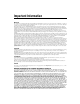
Chapter 5 Using the SCXI-1125 es Y Create Task Using DAQ Assistant? No Create a Task Programmatically Yes Create Task in DAQ Assistant or MAX Create Channel (Application Specific) Create Another Channel? No Hardware Timing/Triggering? No Further Configure Channels? No Yes Yes Adjust Timing Settings Configure Channels Yes Analyze Data? Process Data Start Measurement Yes No Display Data? Graphical Display Tools Read Measurement Yes No Continue Sampling? No Stop Measurement Clear Task
Chapter 5 Using the SCXI-1125 General Discussion of Typical Flowchart The following sections discuss briefly considerations for a few of the steps in Figure 5-1. These sections give an overview of some of the options and features available when programming with NI-DAQmx. Creating a Task Using DAQ Assistant or Programmatically When creating an application, first you must decide whether to create the appropriate task using the DAQ Assistant or programmatically in the ADE.
Chapter 5 Using the SCXI-1125 time. For continuous acquisition, you must use a while loop around the acquisition components even if you configured the task for continuous acquisition using MAX or the DAQ Assistant. For continuous and buffered acquisitions, you can set the acquisition rate and the number of samples to read in the DAQ Assistant or programmatically in your application. By default, the clock settings are automatically set by an internal clock based on the requested sample rate.
Chapter 5 Using the SCXI-1125 Acquiring, Analyzing, and Presenting After configuring the task and channels, you can start the acquisition, read measurements, analyze the data returned, and display it according to the needs of your application. Typical methods of analysis include digital filtering, averaging data, performing harmonic analysis, applying a custom scale, or adjusting measurements mathematically.
Chapter 5 Using the SCXI-1125 Table 5-4. Programming a Task in LabVIEW Flowchart Step VI or Program Step Create Task in DAQ Assistant Create a DAQmx Task Name Constant located on the Controls»Modern»I/O»DAQmx Name Controls subpalette, right-click it, and select New NI-DAQmxTask (MAX...). Create a Task Programmatically (optional) DAQmx Create Task.vi—This VI is optional if you created Create AI Channel (optional) DAQmx Create Virtual Channel.
Chapter 5 Using the SCXI-1125 Table 5-4. Programming a Task in LabVIEW (Continued) Flowchart Step VI or Program Step Display Data You can use graphical tools such as charts, gauges, and graphs to display your data. Some display tools are located on the Controls»All Controls»Numeric»Numeric Indicators subpalette and Controls»All Controls»Graph subpalette. Continue Sampling For continuous sampling, use a While Loop. If you are using hardware timing, you also need to set the DAQmx Timing.
Chapter 5 Using the SCXI-1125 7. Change the property to read or write to either get the property or write a new value. Right-click the property, go to Change To, and select Write, Read, or Default Value. 8. After you have added the property to the property node, right-click the terminal to change the attributes of the property, add a control, constant, or indicator. Figure 5-2. LabVIEW Channel Property Node with Lowpass Frequency Set at 10 kHz on Channel SC1Mod1/ai0 9.
Chapter 5 Using the SCXI-1125 Follow the general programming flowchart or open an example to build a basic virtual channel. You can use property nodes in LabVIEW to control, configure, and customize the NI-DAQmx task and SCXI-1125. To create a LabVIEW property node, complete the following steps: 1. Launch LabVIEW. 2. Create the property node in a new Virtual Instrument (VI) or in an existing VI. 3. Open the block diagram view. 4.
Chapter 5 Using the SCXI-1125 Text Based ADEs You can use text based ADEs such as LabWindows/CVI, Measurement Studio, Visual Basic, .NET, and C# to create code for using the SCXI-1125. LabWindows/CVI LabWindows/CVI works with the DAQ Assistant in MAX to generate code for a task. You can then use the appropriate function call to modify the task. To create a configurable channel or task in LabWindows/CVI, complete the following steps: 1. Launch LabWindows/CVI. 2. Open a new or existing project. 3.
Chapter 5 Using the SCXI-1125 Table 5-5. NI-DAQmx Properties Property Short Name Description Analog Input»General Properties» Advanced»Range»High AI.Max Specifies the upper limit of the input range. Analog Input»General Properties» Advanced»Range»Low AI.Min Specifies the lower limit of the input range. Analog Input»General Properties» Advanced»Gain and Offset» Gain Value AI.Gain Specifies a gain factor to apply to the signal conditioning portion of the channel.
Chapter 5 Using the SCXI-1125 Traditional NI-DAQ (Legacy) in LabVIEW LabVIEW is a graphical programming environment for test and measurement application development with built-in easy to use tools for data acquisition, analysis, and display. You can use functional graphical blocks called subVIs to easily create a custom application that fully utilizes the SCXI-1125 programmable functionality.
Chapter 5 Using the SCXI-1125 Typical Program Flow After you have determined how you want to address the channels and whether you want to configure the SCXI-1125 in MAX or LabVIEW, you can design your application using a typical program flow such as the one shown in Figure 5-3.
Chapter 5 Using the SCXI-1125 Configure the SCXI-1125 Settings Using Traditional NI-DAQ (Legacy) in LabVIEW You can configure SCXI-1125 settings in MAX using the virtual channel. To configure and control the SCXI-1125 from LabVIEW, use the AI Parameter VI. You can find AI Parameter VI in the function subpalette Data Acquisition»Analog Input»Advanced Analog Input. A parameter changed by the AI Parameter VI takes effect in hardware when AI Start VI is called, not when AI Parameter VI is called.
Chapter 5 Using the SCXI-1125 An example of using the AI Parameter VI to control an SCXI-1125 is shown in Figure 5-4. Figure 5-4.
Chapter 5 Using the SCXI-1125 Convert Scaling Using Traditional NI-DAQ (Legacy) in LabVIEW If you need scaling, you can either use an analog input voltage virtual channel with a custom scale configured in MAX or SCXI channel strings, and provide scaling in your LabVIEW application. If you are using SCXI channel strings, you can easily convert the SCXI-1125 voltage signal measurements in your application into scaled units of interest such as pounds or newtons.
Chapter 5 Using the SCXI-1125 Traditional NI-DAQ (Legacy) in Text-Based ADEs NI text-based ADEs, such as LabWindows/CVI, Measurement Studio for Microsoft Visual Basic, and Measurement Studio for Microsoft Visual C++, offer help in the development of test and measurement applications. These ADEs provide easy data acquisition, data analysis, graphical display, and data logging tools. Refer to the ADE user manual for more information about how to use these features.
Chapter 5 Using the SCXI-1125 Table 5-7. Configuration Functions Function SCXI_Reset Description Resets the hardware such as the specified module to its default state. You also can use SCXI_Reset to reset the SCXI chassis Slot 0 scanning circuitry or reset the entire chassis. The SCXI-1125 default conditions are: • Gain set at 1000.0 • 4 Hz lowpass filter SCXI_Load_Config Loads the SCXI chassis configuration information you established in MAX.
Chapter 5 Using the SCXI-1125 Table 5-8. NI-DAQ Functions Used to Configure SCXI-1125 Channel Setting Significant Parameters NI-DAQ Function to Use Possible Parameters Values Gain SCXI_Set_Gain f64 gain (gain setting) 1, 2, 5, 10, 20, 50, 100, 200, 250, 500, 1000, 2000 Bandwidth SCXI_Configure_Filter f64 freq (filter cutoff frequency if filterMode = 1) 4.0, 10,000.
Chapter 5 Using the SCXI-1125 the data corresponds to a scanned channel for easier access by C applications. BASIC applications need not call SCAN_Demux to rearrange two-dimensional arrays since these arrays are accessed in column-major order. For more information regarding each acquisition function, refer to the Traditional NI-DAQ (Legacy) Function Reference Help installed by default in Start»Programs»National Instruments» NI-DAQ.
Chapter 5 Using the SCXI-1125 support virtual channels using Data Neighborhood (DAQ Channel Wizard) in MAX. In LabWindows/CVI, C, or C++ development environments, several NI-DAQ function calls need to be made to set up each module involved in the scan, the chassis, and the E Series DAQ device controlling the scan. In Measurement Studio, SCXI channels must be configured as virtual channels (tags) in MAX. A discussion describing how to implement multiplexed scanning in the different ADEs follows.
Chapter 5 Using the SCXI-1125 The last parameter, channels, is the list of channels that are scanned for module z. It can have several formats: • obx ! scy ! mdz ! n, where n is a single input channel. • obx ! scy ! mdz ! n1:n2, where n1 and n2 represent a sequential list of input channels, inclusive. • obx ! scy ! mdz ! cjtemp, where cjtemp is the CJC channel. You can scan this channel with other analog input channels. For compatibility reasons, you can use mtemp in place of cjtemp.
Chapter 5 Using the SCXI-1125 You cannot mix virtual channels with the SCXI channel strings shown in the previous section. Note To create a virtual channel for the SCXI-1125, insert a new analog input channel in the Data Neighborhood path in MAX, name it, and then follow the software prompts to create virtual temperature channels, voltage channels, or customized analog input channels. For more information on virtual channels, consult the MAX online help file.
Chapter 5 Using the SCXI-1125 C and Low-Level DAQ Functions When using a C-based environment, several steps are needed to configure the SCXI-1125 for multiplexed scanning. The following procedure outlines the steps for programming with the low-level DAQ function calls: 1. Prepare the SCXI-1125 settings by either loading the original SCXI configuration settings using SCXI_Load_Config, or by specifying the gain and filter settings using SCXI_Set_Gain and SCXI_Configure_Filter. 2.
Chapter 5 Using the SCXI-1125 After parallel mode has been configured in software, you can scan the SCXI-1125 channels by entering the corresponding E Series DAQ device channels or a sequential SCXI channel string in the channel parameter in the analog input application. You can also enter virtual channels; however, in parallel mode, virtual channels containing CJC are disabled in MAX.
Chapter 5 Using the SCXI-1125 Calibration The SCXI-1125 is shipped with a calibration certificate and is calibrated by the factory to the specifications described in Appendix A, Specifications. Calibration constants are stored inside the calibration EEPROM and provide software correction values that are used by your application development software to correct your measurements for both offset and gain errors in the module.
Chapter 5 Using the SCXI-1125 One-Point Offset Calibration To perform offset calibration on your module, follow this procedure if you are using LabVIEW: 1. Make sure the DAQ device or DMM you are using has a valid calibration and meets the accuracy specifications for your application. 2. In LabVIEW, use the SCXI Calibrate VI to calibrate your module. a. Enter the DAQ device and the SCXI channel string for the channels you want to calibrate.You can calibrate only one channel at a time. b.
Chapter 5 Using the SCXI-1125 Table 5-9. Gain Values and Input Limits (Continued) Gain Range (±) 1000 0.005 V 2000 0.0025 V If you are using a C-based ADE, use the following procedure to do an offset calibration on the SCXI-1125: 1. Make sure the DAQ device or DMM you are using has a valid calibration and meets the accuracy specifications for your application. 2. Use the NI-DAQ function SCXI_Calibrate to calibrate one channel of the SCXI-1125. 3. a.
A Specifications This appendix lists the specifications for the SCXI-1125 modules. These specifications are typical at 25 °C unless otherwise noted. Input Characteristics Table A-1. Input Signal Range Versus Gain Overall Gain Overall Voltage Range SCXI-1125 Gain 1 ±5 Vpeak or VDC 1 2 ±2.
Appendix A Specifications Overvoltage protection Isolated connector pins: Powered on and off..........................±300 V Inputs protected ...............................CH0..CH7 Non-isolated connector pins: Powered on and off..........................+5.5V/– 0.5 V SCXI-1125 User Manual A-2 ni.
0.005 0.02 0.05 ±1000 VDC1, 2, 3 V4 ±100 V4 © National Instruments Corporation A-3 10 20 50 100 200 ±500 mV ±250 mV ±100 mV ±50 mV ±25 mV 250 5 ±1 V ±20 mV 2 ±10 ±2.5 V 0.5 V4 ±25 1 0.2 V4 ±5 V 0.1 ±50 V4 ±250 Overall Gain Nominal Range Absolute Accuracy 0.08 0.08 0.07 0.07 0.07 0.07 0.07 0.07 0.07 0.2548 0.2548 0.2548 0.2548 0.2548 0.3996 Typical 0.53 0.52 0.52 0.52 0.52 0.52 0.52 0.52 0.52 0.65 0.65 0.65 0.65 0.65 1.25 Max % of Reading 1.
SCXI-1125 User Manual 0.10 μV 2.5 μV 3.2 μV With SCXI-1327 high-voltage terminal block. 11.2 μV 0.17 μV 4.70 μV 10 kHz With TBX-1316 high-voltage terminal block. 0.42 μV 15 μV 14.9 μV 0.27 μV 4 Hz 4 0.54 0.72 μV 15 μV 21.8 μV 10 kHz Vrms refers to sinusoidal waveform; V refers to DC or AC peak. 0.09 0.53 1.3 μV 20 μV 4 Hz 3 2000 ±2.5 mV 0.08 0.53 Offset Absolute accuracy (15 to 35 ºC). To calculate the absolute accuracy for the SCXI-1125 visit ni.com/accuracy.
Appendix A Specifications Analog Inputs Number of input channels ...................... 8 differential Input range ............................................. ± 2.5 mVDC to ±5 VDC Input coupling ........................................ DC (or AC with SCXI-1305 or TBX-1329) Input impedance Normal powered on ........................ >1 G || 100 pF in parallel Powered off/overload...................... 4.5 M With SCXI-1327 ............................. 1 M With TBX-1316 ..............................
Appendix A Specifications Normal Mode Rejection, 50/60 Hz (NMRR) 4 Hz filter enabled ...........................60 dB Crosstalk at 1kHz Adjacent channels............................–75 dB All other channels............................– 90 dB Input coupling Default .............................................DC Using SCXI-1305 or TBX-1329 .....AC or DC Power Consumption +18.5 V ...................................................140 mA max – 18.5 V ..................................................
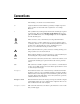
Appendix A Specifications Physical 3.0 cm (1.2 in.) 17.2 cm (6.8 in.) 18.8 cm (7.4 in.) Figure A-1. SCXI-1125 Dimensions Weight .................................................... 641 g (22.
Appendix A Specifications Maximum Working Voltage Maximum voltage rating refers to the signal voltage plus the common mode voltage (Signal + common mode). Voltage of each input shall remain within 300 V of ground. Channel-to-earth .....................................300 V, Measurement Category II Channel-to-channel.................................300 V, Measurement Category II Table A-2.
Appendix A Specifications Safety This product is designed to meet the requirements of the following standards of safety for electrical equipment for measurement, control, and laboratory use: • IEC 61010-1, EN-61010-1 • UL 61010-1, CSA 61010-1 Note For UL and other safety certifications, refer to the product label or visit ni.com/ certification, search by model number or product line, and click the appropriate link in the Certification column.
Appendix A Specifications Environmental Management National Instruments is committed to designing and manufacturing products in an environmentally responsible manner. NI recognizes that eliminating certain hazardous substances from our products is beneficial not only to the environment but also to NI customers. For additional environmental information, refer to the NI and the Environment Web page at ni.com/environment.
Using SCXI Channel Strings with Traditional NI-DAQ (Legacy) 7.0 or Later B This appendix is not applicable if you use the virtual channels to configure and measure the SCXI channels. Virtual channels are configured using MAX. If you use virtual channels, you address the SCXI channels by specifying the channel name(s) in the channel string input. Note When using LabVIEW, and Visual Basic, the SCXI channel string determines which SCXI channels are scanned and the scanning sequence.
Appendix B Using SCXI Channel Strings with Traditional NI-DAQ (Legacy) 7.0 or Later channels is the list of channels that are scanned for module z. It can have several formats: • obx ! scy ! mdz ! nx, where nx is a single input channel. • obx ! scy ! mdz ! (n0, n2), where n0, n2 are individual input channel that are not necessarily sequential. • obx ! scy ! mdz ! n0:n3, where n0 and n3 represent an ascending sequential list of input channels, inclusive.
Removing the SCXI-1125 C This appendix explains how to remove the SCXI-1125 from MAX and an SCXI chassis. Figure C-1 shows an SCXI chassis, but the same steps are applicable to a PXI/SCXI combination chassis. Note Removing the SCXI-1125 from MAX To remove a module from MAX, complete the following steps after launching MAX: 1. Expand Devices and Interfaces to display the list of installed devices and interfaces. 2. Expand NI-DAQmx Devices and/or Traditional NI-DAQ Devices to display the chassis. 3.
Appendix C Removing the SCXI-1125 2. If the SCXI-1125 is the module cabled to the E Series DAQ device, disconnect the cable. 3. Remove any terminal block that connects to the SCXI-1125. 4. Rotate the thumbscrews that secure the SCXI-1125 to the chassis counterclockwise until they are loose, but do not completely remove the thumbscrews. 5. Remove the SCXI-1125 by pulling steadily on both thumbscrews until the module slides completely out.
D Common Questions This appendix lists common questions related to the use of the SCXI-1125. The SCXI-1125 is backward compatible with the SCXI-1120, but what are the major differences between the SCXI-1120 and the SCXI-1125? Table D-1 compares the major specifications and features of the two modules. Other specifications and features of the SCXI-1125 are the same or very similar to the SCXI-1120. Table D-1.
Appendix D Common Questions Which version of NI-DAQ is needed to work with the SCXI-1125 and how do I get the most current version of NI-DAQ? You must have NI-DAQ 7.0 or later. Visit ni.com and follow the link, Download Software»Drivers and Updates»Search Drivers and Updates, and type in the keyword NI-DAQ to find the latest version of NI-DAQ for your operating system.
Appendix D Common Questions Table D-2. Digital Signals on the SCXI-1125 Traditional DAQ Signal Name DAQmx Signal Name SCXI Signal Name 50-Pin Connector 68-Pin Connector Direction DIO0 P0.0 SER DAT IN 25 52 Output DIO4 P0.4 SER DAT OUT 26 19 Input DIO1 P0.1 DAQ D*/A 27 17 Output DIO2 P0.
Appendix D Common Questions In LabVIEW, can I use a VI to change my filter setting? In NI-DAQmx, you can change the filter settings using a DAQmx Channel property node. In Traditional NI-DAQ (Legacy), there is no VI available to do this. You must use the configuration utility in MAX to configure the filter setting of each channel.
Glossary Symbol Prefix Value p pico 10 – 12 n nano 10 – 9 μ micro 10 – 6 m milli 10 – 3 k kilo 10 3 M mega 10 6 G giga 10 9 T tera 10 12 Numbers/Symbol ° Degrees. ≥ Greater than or equal to. ≤ Less than or equal to. Ω Ohms. / Per. % Percent. ± Plus or minus. +5 V (signal) +5 VDC source signal.
Glossary A A/D analog-to-digital absolute accuracy The maximum difference between the measured value from a data acquisition device and the true voltage applied to the input, typically specified as ± voltage. AC alternating current ADC analog-to-digital converter—An electronic device, often an integrated circuit, that converts an analog voltage to a digital number.
Glossary C C Celsius CE Conformité Européenne—The European emissions control standard. The CE mark certifies that a product complies to relevant CE regulations. CE is a common standard for all countries in the EU (European Union). CH channel channel Pin or wire lead to which you apply or from which you read an analog or digital signal. Analog signals can be single-ended or differential. For digital signals, channels group to form ports. Ports usually consist of either four or eight digital channels.
Glossary DAQ Data acquisition—(1) collecting and measuring electrical signals from sensors, transducers, and test probes or fixtures and inputting them to a computer for processing; (2) collecting and measuring the same kinds of electrical signals with A/D and/or DIO boards plugged into a computer, and possibly generating control signals with D/A and/or DIO boards in the same computer. DAQ device A device that collects signals for data acquisition devices. Examples are MIO and 1200 boards.
Glossary F filtering A type of signal conditioning that allows you to remove unwanted signal components from the signal you are trying to measure. FSR full-scale range G gain The factor by which a signal is amplified, sometimes expressed in decibels. gain accuracy A measure of deviation of the gain of an amplifier from the ideal gain. gain error See gain accuracy.
Glossary isolation A type of signal conditioning in which you isolate the transducer signals from the computer for safety purposes. Isolating the signals protects you and your computer from large voltage spikes and makes sure the measurements from the DAQ device are not affected by differences in ground potentials. isothermal Maintenance of constant temperature across an area. Isothermal construction of terminal blocks increases thermocouple measurement accuracy.
Glossary multiplexed mode An SCXI operating mode in which analog input channels are multiplexed into one module output so that your cabled DAQ device has access to the module’s multiplexed output as well as the outputs on all other multiplexed modules in the chassis through the SCXIbus.
Glossary ppm parts per million PXI A rugged, open system for modular instrumentation based on CompactPCI, with special mechanical, electrical, and software features. The PXIbus standard was originally developed by National Instruments in 1997, and is now managed by the PXIbus Systems Alliance. R resolution The smallest signal increment that can be detected by a measurement system. Resolution can be expressed in bits, in proportions, or in percent of full scale.
Glossary SCXI Signal Conditioning eXtensions for Instrumentation—the National Instruments product line for conditioning low-level signals within an external chassis near sensors so only high-level signals are sent to DAQ boards in the noisy PC environment. SCXIbus The analog bus where SCXI analog signals are routed. SER CLK A serial clock signal used to synchronize digital data transfers over the SER DAT IN and SER DAT OUT lines.
Glossary T thermocouple A temperature sensor created by joining two dissimilar metals. The junction produces a small voltage as a function of the temperature.
Index A common questions, D-1 configuration troubleshooting self-test verification, 1-7 configuration settings filter bandwidth, 3-1, 4-2 gain, 3-1, 4-1 connecting SCXI-1125 to DAQ device See also DAQ devices for parallel scanning, 1-5 connectors front signal connector pin assignments figure, 2-6 table, 2-6 rear signal connector description, 2-7 pin assignments figure, 2-8 table, 2-8 conventions used in the manual, iv AC and DC voltage connections, 2-1 AC-coupling, 2-4 floating AC-coupled signal connectio
Index I digital lines, unavailability on DAQ device, D-2 digital signals on SCXI-1125 (table), D-3 documentation conventions used in the manual, iv input characteristics, A-1 installation connecting SCXI-1125 to DAQ device for parallel scanning, 1-5 connecting to DAQ device for multiplexed scanning in PXI combination chassis, 1-4, 3-2 in SCXI chassis, 1-4, 3-2 into SCXI chassis, 1-4 removing SCXI-1125 from Measurement & Automation Explorer, C-1 from SCXI chassis, C-1 E electromagnetic compatibility spec
Index theory of multiplexed hardware operation, 4-3 using software for scanning operations LabVIEW and SCXI channel string, 5-25 LabVIEW and virtual channel string, 5-26 multiplexed mode operation connecting to SCXI-1125 for DAQ device in PXI combination, 1-4, 3-2 in SCXI chassis, 1-4, 3-2 removing SCXI-1125 from Measurement & Automation Explorer, C-1 from SCXI chassis, C-1 S safety specifications, A-9 SCXI channel string, 5-25 SCXI chassis connecting SCXI-1125 to DAQ device, 1-4, 3-2 SCXI-1125 calibrati
Index T front connector pin assignments (table), 2-6 overview, 2-1 temperature sensor connection, 2-7 software multiplexed scanning operations, 5-24 LabVIEW and SCXI channel string, 5-25 LabVIEW and virtual channel string, 5-26 parallel scanning operations C and parallel mode, 5-29 LabVIEW and parallel mode, 5-28 specifications electromagnetic compatibility, A-9 environmental, A-8 input characteristics, A-1 maximum working voltage, A-8 physical, A-7 regulatory compliance, A-9 safety, A-9 stability, A-6 tr