Click here to comment on this document via the National Instruments website at http://www.natinst.com/documentation/daq/ Measure® Data Acquisition User Manual August 1996 Edition Part Number 321004B -01 © Copyright 1995, 1996 National Instruments Corporation. All rights reserved.
Internet Support Email: measure.support@natinst.com National Instruments Home Page: http://www.natinst.com FTP Site: ftp.natinst.com Bulletin Board Support BBS United States: (512) 794-5422 or (800) 327-3077 BBS United Kingdom: 01635 551422 BBS France: 1 48 65 15 59 FaxBack Support (512) 418-1111 Telephone Support (U.S.
Important Information Warranty The media on which you receive National Instruments software are warranted not to fail to execute programming instructions, due to defects in materials and workmanship, for a period of 90 days from date of shipment, as evidenced by receipts or other documentation. National Instruments will, at its option, repair or replace software media that do not execute programming instructions if National Instruments receives notice of such defects during the warranty period.
About This Manual Organization of This Manual Conventions Used in This Manual Customer Communication xi Chapter 1 Introduction Using Measure with Your DAQ Device DAQ Device Overview Installing Measure Manually Adding or Removing the DAQ Add-In Uninstalling Measure Chapter 2 Getting Started with Data Acquisition Tasks Selecting a Data Acquisition Task Configuring an Analog Input Task Configuring an Analog Output Task Adding Tasks to the DAQ Menu Saving Tasks Managing Tasks in a Workbook Chapter 3 Using S
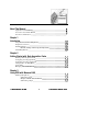
Table of Contents Chapter 4 Analog Input Reference DAQ Device Overview Analog Input Configuration Overview Analog Input Scan List Channels High Limit Low Limit Scan Information Number of scans Scale to volts Timing Settings Scans/second External scan clock Display At cell In Columns In Rows Trigger Reference Mode Reference Advanced Timing Settings Chapter 5 Analog Output Reference Analog Output Configuration Overview Advanced Configuration Chapter 6 Using Measure Data Acquisition Tasks with VBA Function
Table of Contents Appendix B Error Codes Appendix C Trouble Shooting Appendix D Customer Communication Glossary Index Figures Figure 1-1. Add-Ins Dialog Box Figure 2-1. Figure 2-2. Figure 2-3. Figure 2-4. Figure 2-5. Figure 2-6. Figure 2-7. Figure 2-8. Figure 2-9. DAQ Tasks Dialog Box Analog Input Configuration Task Description Dialog Box DAQ Tasks Dialog Box Analog Output Configuration Dialog Box DAQ Tasks Dialog Box Adding Tasks to the DAQ Menu The DAQ Menu DAQ Tasks Dialog Box Figure 3-1.
Table of Contents Tables Table 2-1. DAQ Tasks Dialog Box Options Table 3-1. SCXI Channel Strings Syntax Table 4-1. Table 4-2. Table 4-3. Table 4-4. Table 4-5. Table 5-1. Table 5-2. Examples of Valid Channel Strings Analog Input Configuration Buttons/Options Choices for Hardware Digital Trigger Choices for Analog Input Mode Dialog Box Choices for Advanced Timing Analog Output Configuration Reference Advanced Analog Output Configuration Options Table A-1. Table A-2. Table A-3. Table A-4. Table A-5.
The Measure Data Acquisition User Manual describes how to use the Measure Data Acquisition Add-In with National Instruments data acquisition boards to acquire data into Microsoft Excel. You should be familiar with the operation of Microsoft Excel, your computer, your computer’s operating system, and your data acquisition (DAQ) board. Organization of This Manual The Measure Data Acquisition User Manual is organized as follows.
About This Manual • Chapter 6, Using Measure Data Acquisition Tasks with VBA, describes how to run tasks from within Visual Basic for Applications. • Appendix A, DAQ Hardware Capabilities, contains SCXI information and tables that summarize the analog I/O capabilities of National Instruments data acquisition devices you might use with Measure for Windows. • Appendix B, Error Codes, describes the errors that can occur while using the Measure DAQ Add-In.
About This Manual monospace Text in this font denotes text or characters that are to be literally input from the keyboard, sections of code, programming examples, and syntax examples. This font is also used for the proper names of disk drives, paths, directories, programs, subprograms, subroutines, device names, functions, variables, filenames, and extensions, and for statements and comments taken from program code.
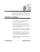
Introduction This chapter helps you install the Measure Data Acquisition (DAQ) Add-In. You should have installed and configured your DAQ hardware already. If you have not done so, please refer to the NI-DAQ User Manual for PC Compatibles that came with your device for instructions on installation and configuration. Using Measure with Your DAQ Device Measure is designed to work with many different National Instruments DAQ devices.
Chapter 1 Introduction DAQ Device Overview Measure is an easy-to-use spreadsheet interface for acquiring data with a wide range of National Instruments DAQ devices. Because Measure works with so many different devices, the functionality and performance of the software often varies based on the particular DAQ device you use. Although Measure senses the type of DAQ device you are using, you might select options in the task configuration that are not supported by your particular device.
Chapter 1 Introduction Manually Adding or Removing the DAQ Add-In To add the DAQ Add-In manually, complete the following steps. 1. Select Tools»Add-Ins. 2. In the Add-Ins dialog box, search the Add-Ins Available list box for the Measure Data Acquisition Add-In entry. Click in the checkbox next to the Measure Data Acquisition Add-In entry. If you cannot find the entry, click the Browse button and look for DAQ.XLA in the directory where you installed Measure.
Getting Started with Data Acquisition Tasks After you install and configure your hardware and install the Measure Data Acquisition Add-In, you are ready to acquire data. This chapter contains a tutorial for each of the following basic functions.
Chapter 2 Getting Started with Data Acquisition Tasks Figure 2-1. DAQ Tasks Dialog Box The DAQ Tasks dialog box manages the I/O operations, or tasks, that you define with Measure. From this dialog box, you can create new tasks, edit existing tasks, and run I/O tasks interactively to test their operation. 3. Select a DAQ device from the Data acquisition device drop-down listbox at the top of the dialog box.
Chapter 2 Getting Started with Data Acquisition Tasks Figure 2-2. Analog Input Configuration Configuring an Analog Input Task From the Analog Input Configuration dialog box, you can specify all the parameters for an analog input operation. In the following steps, you create a simple analog input task. Refer to Chapter 4, Analog Input Reference, for more detailed information about the different options for analog input. 1.
Chapter 2 Getting Started with Data Acquisition Tasks example in which there is only one channel specified, the number of scans is equal to the number of points acquired from channel 0. If you were to specify two channels in your channel list, 100 scans would result in 200 points of data acquired (100 from each channel). Type 100 in the Number of Scans field. 3. The Scan Rate section of the dialog box is where you specify how fast you would like to acquire the data.
Chapter 2 7. Getting Started with Data Acquisition Tasks Click on the OK button to return to the DAQ Tasks dialog box, shown in Figure 2-4. Notice that you now have a task named Read Channel 0 in your task list. Notice also that the description for this new task appears in the dialog box as well. Figure 2-4. DAQ Tasks Dialog Box 8. Click on the Run button to execute the task. When the task completes, there are 100 datapoints in column A of your worksheet.
Chapter 2 Getting Started with Data Acquisition Tasks 1. From the DAQ Task dialog box, select AO from the Create a task section of the dialog box to display the Analog Output Configuration dialog box, shown in Figure 2-5. Figure 2-5. Analog Output Configuration Dialog Box 2. Type 0 in the Channel input field. 3. Type $A$1:$A$10 in the Data cells input field. You manually can type this range, or highlight the input field and drag particular areas of your worksheet to specify a cell range.
Chapter 2 Getting Started with Data Acquisition Tasks dialog box. Notice that your new analog output task appears in the task list, shown in Figure 2-6. Figure 2-6. DAQ Tasks Dialog Box 10. Highlight the Output 10 iterations task and click on the Run button to execute the analog output task. Make sure you have valid voltage data in cells A1:A10 before running the task.
Chapter 2 Getting Started with Data Acquisition Tasks Figure 2-7. Adding Tasks to the DAQ Menu 3. Highlight each of the tasks in the window on the right and click on the Add button to add them to the DAQ menu. 4. Click on the OK button to return to the Configure DAQ Tasks menu. Click on the OK button to return to the Excel worksheet. 5. Pull down the DAQ menu. Notice that two new entries now appear in the DAQ menu, shown in Figure 2-8.
Chapter 2 Getting Started with Data Acquisition Tasks Your tasks are saved as part of the Excel workbook. Each time you launch Excel and open a workbook that contains Measure tasks, they appear in the task list of the DAQ tasks dialog box. Managing Tasks in a Workbook This section describes how to use the DAQ Tasks dialog box, shown in Figure 2-9, to manage the tasks in a workbook. You can open this dialog box by selecting DAQ»ConfigureDAQTasks from the menu bar. Figure 2-9.
Chapter 2 Getting Started with Data Acquisition Tasks Table 2-1 contains a list of the DAQ Tasks dialog box options with descriptions of their use. Table 2-1. DAQ Tasks Dialog Box Options Option/Button Description Data acquisition device Select the National Instrument data acquisition device for which you want to create a task. Measure scans your NI-DAQ configuration for installed devices and lists only those devices that Measure supports.
Using SCXI with Measure DAQ This chapter describes how to use the Measure data acquisition (DAQ) Add-in in Excel with your Signal Conditioning Extension for Instrumentation (SCXI) equipment. SCXI is a set of modules and terminal blocks used as a signal condition front-end for your data acquisition devices. These modules perform tasks such as multiplexing large numbers of signals, amplifying lowlevel signals, providing isolation between your data acquisition devices and transducers, and so on.
Chapter 3 Using SCXI with Measure DAQ your data acquisition device. The multiplexed mode is the default and recommended mode to use with SCXI. In the parallel mode, each SCXI module is directly connected to one data acquisition device and each analog input channel on a SCXI module is connected to a separate analog input channel on the data acquisition device. Not all data acquisition devices or SCXI modules support the parallel mode. Consult your data acquisition hardware user manual for more information.
Chapter 3 Using SCXI with Measure DAQ ‘z’ in the SCXI channel string represents the actual channel number (e.g. 3). Channels on the SCXI modules are numbered starting at zero. You specify a range of channels on your SCXI modules by listing the first and last channel separated with a colon (e.g. 0:5). You only use the SCXI channel string when the SCXI is operating in multiplexed mode and channels are multiplexed onto one or more channels of the data acquisition device.
Chapter 3 Using SCXI with Measure DAQ Figure 3-1. Selecting the Add>> button Table 3-1 lists other possible combinations for SCXI channel strings. Table 3-1. SCXI Channel Strings Syntax String Syntax Description ob0!sc1!md2!5 Channel 5 on module 2 of SCXI chassis 1 is read through onboard channel 0. ob0!sc1!md2!0:7 ob0!sc1!md4!5:12 Channels 0-7 on module 2 and channels 5-12 on module 4 of chassis 1 are read through onboard channel 0.
Chapter 3 Using SCXI with Measure DAQ SCXI Analog Output The current version of Measure does not support the use of analog output (AO) channels on the SCXI-1124 module. You can use the analog output channels of the SCXI-1200 module by selecting the device number and the AO channel number as you would with any other DAQ device.
Analog Input Reference This chapter introduces some basic concepts of data acquisition and contains a reference for analog input configuration, hardware digital triggering, analog input modes, and advanced timing. You should be familiar with the hardware capabilities of your data acquisition device. DAQ Device Overview Measure works with a wide variety of National Instrument DAQ devices. This chapter provides a technical overview and reference information about using Measure for analog input operations.
Chapter 4 Analog Input Reference Analog Input Configuration Overview Select DAQ»Configure DAQ Tasks and then press the AI button to open the Analog Input Configuration dialog box, shown in Figure 4-1. The sections below describe the fields within the Analog Input Configuration dialog box, and Table 4-2 explains the remaining options at the bottom of the Analog Input Configuration dialog box. Figure 4-1.
Chapter 4 Analog Input Reference left-to-right is the order that Measure scans the channels. The following is a table of valid channel strings. Table 4-1.
Chapter 4 Analog Input Reference Low Limit Enter the lower voltage limit for the channels in the channel string. This voltage is the minimum voltage that is measured at any of the analog input channels that are specified in the channel string. You may add more than one channel string to your scan list and each channel string may have a different set of high and low limits. When you create an AI task, Measure enters the default value for your device.
Chapter 4 Analog Input Reference in time the channels are sampled within each scan. The reciprocal of the channel clock rate is called the interchannel delay, or channel interval, shown in Figure 4-2. 0 1 2 3 0 1 2 3 0 1 2 3 scan interval channel interval Figure 4-2. Scan Clock and Channel Clock Measure automatically calculates the smallest, safe interchannel delay for your given configuration and device.
Chapter 4 Analog Input Reference Display When determining where to display the acquired data, Measure uses three pieces of information you specify.
Chapter 4 Mode Description OK Cancel Analog Input Reference Change the analog input mode from the setting that you specify when you run the NI-DAQ Configuration Utility, WDAQCONF.EXE. Measure automatically selects the option that reflects the current setting for your device. Enter a short description of your task. Measure displays a description of a task below the task list in the DAQ Tasks dialog box.
Chapter 4 Analog Input Reference Table 4-3. Choices for Hardware Digital Trigger Choices for Hardware Digital Trigger Description Start acquisition on trigger Select this option if you want to start your acquisition on the rising edge of the PFI0/EXTTRIG/STARTTRIG (depending on the board you are using) input on the connector. Otherwise, Measure starts the acquisition with a software trigger.
Chapter 4 Analog Input Reference Table 4-4 contains a list Analog Input Mode choices with descriptions of their use. Table 4-4. Choices for Analog Input Mode Dialog Box Choices for Analog Input Mode Description Differential Channels Select this option if you want each channel to use two analog channel input lines. One line connects to the positive input of the device amplifier, and the other connects to the negative input of the amplifier.
Chapter 4 Analog Input Reference Advanced Timing Settings Most of the time, you do not have to configure the advanced timing settings because Measure automatically selects reasonable values for you. In some cases, however, you might want to select an interchannel delay or even use an external channel clock. You can configure these settings through the Advanced Timing Settings dialog box, shown in Figure 4-6. Figure 4-6.
Analog Output Reference This chapter introduces some concepts of data acquisition and contains a reference for basic and advanced Analog Output Configuration. You should be familiar with the hardware capabilities of your data acquisition device. Analog Output Configuration Overview To configure an analog output task, first you must select the channels on which you want to generate your signals. Refer to Table 5-1 for detailed information. Figure 5-1.
Chapter 5 Analog Output Reference Table 5-1. Analog Output Configuration Reference Option Description Channel Specify the analog output channel on which to generate a signal. You may only specify one channel at a time. Data cells Specify the source range of the voltage values to write to the digital-toanalog converter (DAC) for the channel.
Chapter 5 Note: Analog Output Reference If you want to generate waveforms on more than one channel, each channel must be added separately to the channel list. Also, Measure requires that all channels have the same number of voltage values to generate. If the range of data for one channel is larger than for another channel in the scan list, the shorter range of data is padded with the value 0 when Measure generates the waveforms.
Chapter 5 Analog Output Reference Table 5-2. Advanced Analog Output Configuration Options Option Description High Limit (volts) The high limit is equal to your reference voltage and is the maximum voltage the DAC can produce. If you have an AT-AO-6/10 board and your Channel Type is current, you can calculate the maximum possible current with the following equation. Imax = Vref + 2.5/0.625 mA The following list contains the default settings for high limit.
Using Measure Data Acquisition Tasks with VBA This chapter describes how to run tasks from within Visual Basic for Applications. There are two ways to execute DAQ Add-In functions in a VBA module. 1. Indirectly, you can use Application.Run returnValue=Application.Run(“FuncName”, arg1) Application.Run “FuncName”, arg1 2. Directly, after you add a reference to the DAQ Add-In. To add a reference to the DAQ Add-In, select Tools»References and select the checkbox next to the Data Acquisition Add-In.
Chapter 6 Using Measure Data Acquisition Tasks with VBA Parameters Option Description TaskName The name of a task in the active workbook. NewTargetRange The address of a range on a worksheet that receives the acquired data. If you fail to specify a worksheet explicitly in the address of this macro, Measure assumes that the range is on the active worksheet. If no worksheet is active, Measure returns an error.
Chapter 6 Using Measure Data Acquisition Tasks with VBA GetDAQErrorMessage Finds and returns a description of an error code returned by the DAQ function. Syntax Function GetDAQErrorMessage(ErrorCode As Integer) As String Parameters Option ErrorCode Description A non-zero number returned by the DAQ function that indicates an error. Return Value A short description of the error code. Example See the previous example for the DAQ function.
DAQ Hardware Capabilities This appendix contains SCXI information, and tables that summarize the analog I/O capabilities of National Instruments data acquisition (DAQ) devices you might use with Measure for Windows. The devices in this appendix are grouped into categories. The DAQ device categories for these tables include the following.
Appendix A DAQ Hardware Capabilities AT-MIO-16/16D Note: By Channel By Device By Device By Device DC “By device” means you select the value of a parameter with hardware jumpers, and the selection affects any group of channels on the device. “By group” means you program the selection through software, and the selection affects all the channels used at the same time. “By channel” means you program the selection with hardware jumpers or through software on a per channel basis.
Appendix A DAQ Hardware Capabilities Table A-3.
Appendix A DAQ Hardware Capabilities Lab and 1200 Series and Portable Devices Hardware Capabilities Table A-5.
Appendix A DAQ Hardware Capabilities Table A-6. Analog Input CharacteristicsLab, 1200 Series, Portable Devices (Part 1) Device Number of Channels Gains1 Resolution (bits) Range (V)1 Input FIFO (samples) Lab-PC+ SCXI-1200 DAQPad-1200 DAQCard-1200 PCI-1200 8SE, 4DI 12 1, 2, 5, 10 20, 50, ±5, 0 to 10 100 DAQCard-500 8SE 12 1 ±5 16 DAQCard-700 16SE, 8DI 12 1 ±10, ±5, ±2.5 512 PC-LPM-16 16SE 12 1 ±5, ±2.
Appendix A DAQ Hardware Capabilities Table A-8. Analog Output CharacteristicsLab, 1200 Series, Portable Devices Device Channel #s Lab-PC+ SCXI-1200 DAQPad-1200 DAQCard-1200 PCI-1200 0, 1 DAC Type 12-bit double-buffered Output Limits (V) 0 to 10, ±5 Waveform Grouping 0, 1, or 0 and 1 SCXI Module Hardware Capabilities Table A-9.
Appendix A SCXI-1141 8 DI ±5 1, 2, 5, 10, 20, 50, 100 1 (SW/C) DAQ Hardware Capabilities elliptic lowpass — filter with 10Hz to 25KHz cutoff 2 (SW/M)1 frequency multiplexed or parallel (disabled on a per channel basis) 1 DS/C = dip switch-selectable per channel, JS/C = jumper-selectable per channel, JS/M = jumper-selectable per module, SW/C = software-selectable per channel, SW/M = software-selectable per module 2 The SCXI-1141 has an automatic filter setting.
Appendix A DAQ Hardware Capabilities Analog Output Only Devices Hardware Capabilities Table A-11. Analog Output CharacteristicsAnalog Output Only Devices Device Channel #s DAC Type Output Limits (V) AT-AO-6 AT-AO-10 0 through 5, 12-bit double6 through 9* buffered with 1 K FIFO for update clock 1 channels ±10V, ±Vref1, 0 to 10, 0 to Vref1, 4 to 20 mA, 4 to Vref1 + 2.5 mA 0.
Error Codes This appendix describes the errors that can occur while using the Measure DAQ Add-In. Table B-1.
Appendix B Error Codes -10010 badCountErr -10011 badIntervalErr -10012 badRangeErr -10013 badErrorCodeErr -10014 -10015 -10016 -10017 -10018 -10019 -10020 -10021 groupTooLargeErr badTimeLimitErr badReadCountErr badReadModeErr badReadOffsetErr badClkFrequencyErr badTimebaseErr badLimitsErr -10022 badWriteCountErr -10023 badWriteModeErr -10024 badWriteOffsetErr -10025 limitsOutOfRange Measure Data Acquisition User Manual The count is too large or too small for the specified counter, or th
Appendix B -10026 badBufferSpec -10027 badDAQEventErr -10028 badFilterCutoffErr -10029 obsoleteFunctionError -10030 badBaudRateError -10031 badChassisIDError -10032 badModuleSlotError -10033 invalidWinHandleError -10034 noSuchMessageError -10080 -10081 -10082 -10083 -10084 -10085 badGainErr badPretrigCountErr badPosttrigCountErr badTrigModeErr badTrigCountErr badTrigRangeErr -10086 -10087 -10088 -10089 badExtRefErr badTrigTypeErr badTrigLevelErr badTotalCountErr © National Instruments
Appendix B Error Codes -10090 badRPGErr -10091 badIterationsErr -10092 lowScanIntervalError -10093 fifoModeError -10100 badPortWidthErr -10120 -10121 -10122 -10123 -10124 -10125 -10200 -10201 -10240 gpctrBadApplicationError gpctrBadCtrNumberError gpctrBadParamValueError gpctrBadParamIDError gpctrBadEntityIDError gpctrBadActionError EEPROMreadError EEPROMwriteError noDriverErr -10241 oldDriverErr -10242 functionNotFoundErr -10243 DSPconfigFileErr Measure Data Acquisition User Manual with
Appendix B -10244 deviceInitErr -10245 osInitErr -10246 communicationsErr -10247 DSPcmosConfigErr -10248 dupAddressErr -10249 intConfigErr -10250 dupIntErr -10251 dmaConfigErr -10252 dupDMAErr -10253 jumperlessBoardErr © National Instruments Corporation Error Codes The driver encountered a hardwareinitialization error while attempting to configure the specified device.
Appendix B Error Codes -10254 DAQCardConfErr -10256 dmaChannel1Error -10257 baseAddressError -10258 dmaChannel1Error -10259 dmaChannel2Error -10260 dmaChannel3Error -10340 noConnectErr -10341 badConnectErr -10342 multConnectErr -10343 SCXIConfigErr -10360 DSPInitErr Measure Data Acquisition User Manual The DAQCard cannot be configured because 1) the correct version of the card and socket services software is not installed, 2) the card in the PCMCIA socket is not a DAQCard, or 3) the
Appendix B -10370 badScanListErr -10400 userOwnedRsrcErr -10401 DSPunknownDeviceErr -10402 deviceNotFoundErr -10403 DSPdeviceSupportErr -10404 -10405 -10406 -10407 -10408 -10409 -10410 noLineAvailErr noChanAvailErr noGroupAvailErr lineBusyErr chanBusyErr groupBusyErr relatedLCGBusyErr -10411 -10412 counterBusyErr noGroupAssignErr © National Instruments Corporation Error Codes Possible reasons for this error are as follows.
Appendix B Error Codes -10413 groupAssignErr -10414 reservedPinErr -10416 DSPDataPathBusyError -10417 SCXIModuleNotSupportedErr or -10344 chassisSynchedError -10345 chassisMemAllocError -10346 badPacketError -10347 chassisCommunicationError -10348 waitingForReprogError -10349 SCXIModuleTypeConflictErr or -10440 sysOwnedRsrcErr Measure Data Acquisition User Manual B-8 group. A group is already assigned, or the specified line or channel is already assigned to a group.
Appendix B -10441 memConfigErr -10442 memDisabledErr -10443 memAlignmentErr -10444 DSPmemFullErr -10445 memLockErr -10446 memPageErr -10447 memPageLockErr -10448 stackMemErr -10449 cacheMemErr -10450 physicalMemErr © National Instruments Corporation Error Codes No memory is configured to support the current data-transfer mode, or the configured memory does not support the current data-transfer mode.
Appendix B Error Codes -10451 virtualMemErr -10452 -10453 noIntAvailErr intInUseErr -10454 noDMACErr -10455 -10456 noDMAAvailErr DMAInUseErr -10457 badDMAGroupErr -10458 -10459 diskFullError DSPDLLInterfaceErr -10460 interfaceInteractionErr -10480 muxMemFullError -10481 bufferNotInterleavedError -10560 -10600 invalidDSPhandleErr noSetupErr -10601 multSetupErr Measure Data Acquisition User Manual B-10 The driver is unable to make the transfer buffer contiguous in virtual memory and
Appendix B -10602 noWriteErr -10603 groupWriteErr -10604 activeWriteErr -10605 endWriteErr -10606 -10607 -10608 notArmedErr armedErr noTransferInProgErr -10609 transferInProgErr -10610 transferPauseErr -10611 badDirOnSomeLinesErr -10612 badLineDirErr -10613 badChanDirErr -10614 badGroupDirErr -10615 masterClkErr © National Instruments Corporation Error Codes No output data has been written into the transfer buffer.
Appendix B Error Codes -10616 slaveClkErr -10617 noClkSrcErr -10618 badClkSrcErr -10619 multClkSrcErr -10620 noTrigErr -10621 badTrigErr -10622 preTrigErr -10623 -10624 postTrigErr delayTrigErr -10625 masterTrigErr -10626 slaveTrigErr -10627 noTrigDrvErr -10628 multTrigDrvErr -10629 invalidOpModeErr -10630 invalidReadErr -10631 noInfiniteModeErr Measure Data Acquisition User Manual The clock configuration for the clock slave is invalid.
Appendix B -10632 someInputsIgnoredErr -10633 invalidRegenModeErr -10634 noContTransferInProgressE rror -10635 invalidSCXIOpModeError -10636 noContWithSynchError -10637 bufferAlreadyConfigError -10680 badChanGainErr -10681 badChanRangeErr -10682 badChanPolarityErr -10683 badChanCouplingErr -10684 badChanInputModeErr -10685 clkExceedsBrdsMaxConvRate -10686 scanListInvalidErr -10687 bufferInvalidErr © National Instruments Corporation B-13 Error Codes Certain inputs were ignored
Appendix B Error Codes -10688 noTrigEnabledErr -10689 digitalTrigBErr -10690 digitalTrigAandBErr -10691 extConvRestrictionErr -10692 chanClockDisabledErr -10693 extScanClockErr -10694 unsafeSamplingFreqErr -10695 DMAnotAllowedErr -10696 multiRateModeErr -10697 rateNotSupportedErr -10698 timebaseConflictErr -10699 polarityConflictErr -10700 signalConflictErr Measure Data Acquisition User Manual The number of total scans and pretrigger scans implies that a triggered start is inten
Appendix B -10701 noLaterUpdateError -10702 prePostTriggerError -10710 noHandshakeModeError -10720 noEventCtrError -10740 SCXITrackHoldErr -10780 sc2040InputModeErr -10781 outputTypeMustBeVoltageEr ror -10782 sc2040HoldModeError -10783 calConstPolarityConflictE rror -10800 timeOutErr -10801 calibrationErr -10802 dataNotAvailErr -10803 transferStoppedErr -10804 earlyStopErr © National Instruments Corporation B-15 Error Codes The call had no effect because the specified channel
Appendix B Error Codes -10805 overRunErr -10806 noTrigFoundErr -10807 earlyTrigErr -10808 LPTCommunicationErr -10809 gateSignalErr -10810 internalDriverError -10811 internalKernelError -10840 softwareErr -10841 firmwareErr -10842 hardwareErr -10843 underFlowErr Measure Data Acquisition User Manual The clock source for the input task is faster than the maximum clock rate the device supports.
Appendix B -10844 underWriteErr -10845 overFlowErr -10846 overWriteErr -10847 dmaChainingErr -10848 noDMACountAvailErr -10849 OpenFileError -10850 -10851 -10852 -10853 -10854 -10855 closeFileErr fileSeekErr readFileErr writeFileErr miscFileErr osUnsupportedError -10856 osError © National Instruments Corporation Error Codes New data was not written to the output transfer buffer before the driver attempted to transfer data to the device.
Appendix B Error Codes -10880 updateRateChangeErr -10881 partialTransferCompleteError -10882 daqPollDataLossError -10883 wfmPollDataLossError -10884 pretrigReorderError -10920 gpctrDataLossErr -10940 chassisResponseTimeoutError -10941 reprogrammingFailedError -10942 invalidResetSignatureError -2001 -2002 ERR_TASK_NOT_FOUND ERR_WORKSHEET_DOES_NOT_EXIST -2003 ERR_RANGE_IS_NOT_VALID Measure Data Acquisition User Manual B-18 A change to the update rate is not possible at this time beca
Appendix B -2101 iERR_AO_MULTIPLE_CHANS_ PER_STRING © National Instruments Corporation Error Codes An analog output channel string represents multiple analog output channels. Measure requires that each analog output channel string contain only one analog output channel.
Troubleshooting This appendix describes solutions to problems that you might encounter using the Measure DAQ Add-In. Problem: No DAQ menu appears. Solution: From the Tools»Add-Ins. Click on the Browse button and look for DAQ.XLA in the directory where you installed Measure. Once you find it, select it and click on the OK button. If a dialog box appears with the message Replace existing ‘DAQ.XLA’? click on the Yes button.
Appendix C Troubleshooting Problem: You are using Windows 3.1 or Windows for Workgroups 3.11 and you get a dialog box entitled Measure with the message, Error -10243 The driver could not locate or open the configuration file, or the format of the configuration file is not compatible with the currently installed driver. Solution: Delete the WDAQCONF.CFG file in your Windows directory. Then reconfigure your hardware using the NI-DAQ Configuration Utility.
Click here to comment on this document via the National Instruments website at http://www.natinst.com/documentation/daq/ Customer Communication For your convenience, this appendix contains forms to help you gather the information necessary to help us solve technical problems you might have as well as a form you can use to comment on the product documentation. Filling out a copy of the Technical Support Form before contacting National Instruments helps us help you better and faster.
Appendix D Customer Communication Click here to comment on this document via the National Instruments website at http://www.natinst.com/documentation/daq/ FaxBack Support FaxBack is a 24-hour information retrieval system containing a library of documents on a wide range of technical information. You can access FaxBack from a touch-tone telephone at the following numbers: (512) 418-1111 E-Mail Support (currently U.S.
Click here to comment on this document via the National Instruments website at http://www.natinst.com/documentation/daq/ Technical Support Form Photocopy this form and update it each time you make changes to your software or hardware, and use the completed copy of this form as a reference for your current configuration. Completing this form accurately before contacting National Instruments for technical support helps our applications engineers answer your questions more efficiently.
Click here to comment on this document via the National Instruments website at http://www.natinst.com/documentation/daq/ Hardware and Software Configuration Form Record the settings and revisions of your hardware and software on the line to the right of each item. Complete a new copy of this form each time you revise your software or hardware configuration, and use this form as a reference for your current configuration.
Click here to comment on this document via the National Instruments website at http://www.natinst.
Click here to comment on this document via the National Instruments website at http://www.natinst.com/documentation/daq/ Documentation Comment Form National Instruments encourages you to comment on the documentation supplied with our products. This information helps us provide quality products to meet your needs. Title: Measure® Data Acquisition User Manual Edition Date: August 1996 Part Number: 321004B-01 Please comment on the completeness, clarity, and organization of the manual.
Prefix Meaning Value pnµmkM- piconanomicromillikilomega- 10-12 10-9 10-6 10-3 103 106 Numbers/Symbols 1D One-dimensional. 2D Two-dimensional. A A/D Analog-to-digital. ADC Analog-to-digital converter. An electronic device, often an integrated circuit, that converts an analog voltage to a digital number. ADC resolution The resolution of the ADC, which is measured in bits. An ADC with 16 bits has a higher resolution, and thus a higher degree of accuracy than a 12-bit ADC. AI Analog input.
Glossary Analog Input Configuration The specification of the analog input channels, input limits, input mode, and scan rate that Measure will use to acquire a waveform. Analog Output Configuration The specification of the analog output channels, output limits, data points, and update rate that Measure will use to generate a waveform. analog trigger A trigger that occurs at a user-selected point on an incoming analog signal.
Glossary C channel Pin or wire lead to which you apply or from which you read the analog or digital signal. Analog signals can be single-ended or differential. For digital signals, you group channels to form ports. Ports usually consist of either four or eight digital channels. channel clock The clock controlling the time interval between individual channel sampling within a scan. Boards with simultaneous sampling do not have this clock.
Glossary DMA Direct memory access. A method by which data you can transfer data to computer memory from a device or memory on the bus (or from computer memory to a device) while the processor does something else. DMA is the fastest method of transferring data to or from computer memory. driver Software that controls a specific hardware device, such as a data acquisition board. E EISA Extended Industry Standard Architecture.
Glossary does not uniquely determine the upper and lower voltage limits. An input range of 10 V could mean an upper limit of +10 V and a lower of 0 V or an upper limit of +5 V and a lower limit of -5 V. The combination of input range, polarity, and gain determines the input limits of an analog input channel. For some boards, jumpers set the input range and polarity, while you can program them for other boards. Most boards have programmable gains.
Glossary output limits The upper and lower voltage or current outputs for an analog output channel. The output limits determine the polarity and voltage reference settings for a board. P PGIA Programmable gain instrumentation amplifier. postriggering The technique you use on a data acquisition board to acquire a programmed number of samples after trigger conditions are met.
Glossary SCXI Signal Conditioning eXtensions for Instrumentation. The National Instruments product line for conditional low-level signals within an external chassis near sensors, so only high-level signals in a noisy environment are sent to data acquisition boards. sec Seconds single-ended inputs Analog inputs that you measure with respect to a common ground. software trigger A programmed event that triggers an event such as data acquisition.
Glossary V V volts. Visual Basic for Applications (VBA) The programming language built into Microsoft Excel. Vref Voltage reference. W waveform Measure Data Acquisition User Manual Multiple voltage readings taken at a specific sampling rate.
A mode reference, 4-8 to 4-9 scan information, 4-4 selecting channels for scanning, 4-2 to 4-3 task configuration, 2-3 to 2-5 timing settings, 4-4 to 4-5 trigger reference, 4-7 to 4-8 Analog Input Configuration dialog box Analog Input Scan List, 2-3, 4-2 to 4-4 At Cell, 4-6 Cancel, 4-7 Channels, 2-3, 4-2 to 4-3 Description, 2-4, 4-7 Display section, 2-4, 4-6 to 4-7 External scan clock, 4-5 Hardware Digital Trigger dialog box, 4-7 to 4-8 High limit, 4-3 illustration, 4-2 In Columns, 4-6 In Rows, 4-6 Low Lim
Index C analog input configuration programmability Lab and 1200 Series and portable devices (table), A-4 MIO and AI devices (table), A-1 to A-2 Analog Input Mode dialog box, 4-8 to 4-9 Differential Channels, 4-9 Non-Referenced Single-Ended Channels, 4-9 Referenced Single-Ended Channels, 4-9 analog output, SCXI modules, 3-5 analog output characteristics analog output only devices (table), A-8 Lab and 1200 Series and portable devices (table), A-6 MIO and AI devices (table), A-3 SCXI modules (table), A-6 to
Index Lab and 1200 Series and portable devices (table), A-4 MIO and AI devices (table), A-3 terminal block selection guide, SCXI modules (table), A-7 DAQ menu adding tasks, 2-7 to 2-8 no menu appears, C-1 DAQ Tasks dialog box managing tasks in workbook, 2-9 to 2-10 options (table), 2-10 purpose and use, 2-2 data acquisition boards. See DAQ devices. Data acquisition device option, DAQ Tasks dialog box, 2-10 data acquisition tasks. See tasks.
Index In Rows option, Analog Input Configuration dialog box, 4-6 installation adding DAQ Add-In manually, 1-3 removing DAQ Add-In manually, 1-3 steps for installation, 1-2 uninstalling Measure, 1-3 interchannel delay specifying, 4-10 Number of scans field, Analog Input Configuration dialog box, 2-4, 4-4 O operating modes, SCXI modules, 3-1 to 3-3 P parallel operating mode, SCXI, 3-1 L R Low Limit field Advanced Analog Output configuration dialog box, 5-4 Analog Input Configuration dialog box, 4-4 Re
Index multiple SCXI modules and chassis, 3-3 to 3-4 analog output, 3-5 configuration, 3-1 operating modes, 3-1 to 3-2 overview, 3-1 Signal Conditioning Extension for Instrumentation (SCXI). See SCXI modules.
Index W waveforms, generating on more than one channel (note), 5-3 WDAQCONF utility, 1-1 workbook, managing tasks in, 2-9 to 2-10 Measure Data Acquisition User Manual I-6 © National Instruments Corporation