FieldPoint TM cFP-20xx Quick Start Guide What You Need to Get Set Up • cFP-20xx LabVIEW RT controller • Mounting hardware (DIN rail, panelmount, or rack-mount accessory) • I/O module(s) • Connectivity accessories: connector blocks, cables • 11–30 V power supply • Accessories: Ethernet cable, screwdriver • PC running Windows • FieldPoint software 3.0.
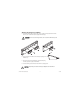
Mounting the Backplane on a DIN Rail A. Fasten the DIN rail clip(s) to the cFP-BP-x using a number 2 Phillips screwdriver and the 8-32 × 5/16 in. countersink screws shipped with the clip(s). CAUTION Do not use screws longer than 5/16 in. to fasten the DIN rail clip to the backplane. L NA S TIO ENT NATRUM INS L NA S TIO ENT NATRUM INS B. Insert one edge of the DIN rail into the deeper opening of the DIN rail clip. C.
Mounting the Backplane on a Panel L NA TS TIO EN NATRUM INS A. Fasten the panel-mount plates to the back of the cFP-BP-x using a number 2 Phillips screwdriver and the 8-32 × 5/16 in. countersink screws shipped with the kit. 102 mm (4 in.) CAUTION Do not use screws longer than 5/16 in. to fasten the panel-mount plates to the backplane. 457 mm (18 in.) C. Connect the PE ground terminal on the cFP-BP-x to safety ground. CAUTION Disconnect power before removing the backplane from the panel.
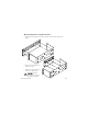
Mounting the Backplane in a Standard 19-in. Rack A. Fasten the rack-mount bracket to the back of the cFP-BP-x using the captive screws on the bracket. L NA TS TIO EN NATRUM INS L NA TS TIO EN NATRUM INS B. Bolt the rack-mount accessory to a standard 19-in. rack. C. Connect the PE ground terminal on the cFP-BP-x to safety ground. CAUTION Disconnect power before removing the backplane from the panel. cFP-20xx Quick Start Guide 4 ni.
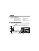
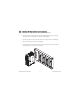
2 Install the cFP-20 xx Controller on the Backplane A. Make sure that no power is connected to the controller or the backplane. B. Make sure that the cFP-20xx controller is right side up with the NI logo at the top, and align the captive screws on the controller with the holes on the backplane. C. Seat the card edge at the back of the controller in the card-edge connector on the backplane. D. Press the controller firmly to seat it on the backplane. E.
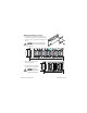
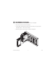
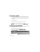
3 Install I/O Modules on the Backplane A. Align the captive screws on the I/O module with the holes on the backplane. B. Press firmly to seat the I/O module on the backplane. C. Using a number 2 Phillips screwdriver with a shank of at least 64 mm (2.5 in.) length, tighten the captive screws to 1.1 N ⋅ m (10 lb ⋅ in.) of torque. D. Repeat this procedure to install additional I/O modules on the backplane. cFP-20xx Quick Start Guide 6 ni.
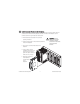
4 Install Connector Blocks on the Backplane In order to connect I/O modules to input signals or to external loads, you need to install a cFP-CB-x connector block or other connectivity accessory for each I/O module on the backplane. Use the connector socket to the right of each I/O module socket. A. Wire field devices as described in the I/O module operating instructions. B. Align the captive screws on the connector block with the holes on the backplane. C.
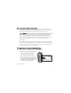
5 Connect the cFP-20xx to Your Network Connect the cFP-20xx controller to an Ethernet network using the RJ-45 Ethernet port on the controller. Use a standard Category 5 Ethernet cable to connect the cFP-20xx to an Ethernet hub, or use an Ethernet crossover cable to connect the controller directly to a computer. CAUTION To prevent data loss and to maintain the integrity of your Ethernet installation, do not use a cable longer than 100 m.
C. Use a separate power supply for each module that needs external power. CAUTION Cascading power defeats isolation between the cascaded modules. D. Refer to the operating instructions for the power requirements of each I/O module. If a module requires external power, connect a power supply to the V and C inputs on the connector block for that module.
8 Install Software on the Host PC A. Install the software packages you plan to use, such as LabVIEW, LabVIEW RT, Lookout, Measurement Studio, or LabWindows/CVI, before you install the FieldPoint software. The FieldPoint software installation installs the LabVIEW VIs and examples, Lookout driver class, and LabWindows/CVI instrument driver only if it finds the corresponding development software installed. B. Close all other applications. C.
C. Click the + sign next to IA Server with OPC in the left pane to expand the view. Right-click FieldPoint and select Add a comm resource to this server. The Comm Resource Configuration dialog box appears. D. Set the Type to Ethernet, as shown in the following figure. Each Ethernet comm resource represents a single FieldPoint network module on the network. E. Click Browse to launch Remote System Explorer.
G. Enter values on the Network Settings tab of the System Configuration dialog box, shown in the figure at right. If your network does not have a gateway server or DNS server, you should set those parameters to 0.0.0.0. • IP Address—The unique, computer-readable address of a device on your network. An IP address is typically represented as four numbers separated by periods (for example, 130.164.55.112), where the numbers can be between 0 and 255, inclusive.
I. Enter an IP address for the Time Server on the Servers tab of the System Configuration dialog box, shown in the figure at right. The time server is a networked computer that runs the National Instruments Time Service installed by FieldPoint Explorer. Enter the IP address of the PC you are using. When you finish configuring the controller, the time has been set and Time Server is not a required parameter.
10 Finding and Configuring Devices and Channels After you have configured the cFP-20xx in FieldPoint Explorer, follow these steps to configure Compact FieldPoint devices and channels. A. In the Comm Resource Configuration dialog box, click Find Devices to search for all of the devices connected to the cFP-20xx. If the Comm Resource Configuration dialog box is not already open, right-click the cFP-20xx in FieldPoint Explorer and select Edit this comm resource.
C. To configure the hardware settings of a particular I/O module, right-click the device name and select Edit this device. The Device Configuration dialog box appears, as shown in the figure above. For output modules, you can choose settings for Watchdog Configuration. Refer to the user manual for information about the network watchdog feature.
D. Click Channel Configuration to access the Channel Configuration dialog box, shown in the figure at right. NOTE Configuration options vary by module. The options listed here may not be available for some modules. Make your selections in this dialog box as follows: 1. Select the type of channel to show, then select the channel(s) that you want to change. To select more than one channel, clear the One channel at a time checkbox. 2. Set the range and output values of the selected channel(s). 3.
© National Instruments Corporation 17 cFP-20xx Quick Start Guide
11 Saving Hardware Configuration as Power-Up State When you are satisfied with the hardware configuration of the FieldPoint system, you can save this configuration as the new power-up state for the system. A. Right-click the cFP-20xx controller in the left pane of FieldPoint Explorer, and select Edit this device. B. Clear the factory configuration checkbox. C.
ni.com Go to ni.com/support for the most current manuals, examples, and troubleshooting information. For telephone support in the United States, create your service request at ni.com/ask and follow the calling instructions or dial 512 795 8248.