
- IMAQ Vision for Measurement Studio User Manual

Chapter 6 Calibration
IMAQ Vision for LabWindows/CVI User Manual 6-2 ni.com
Defining a Calibration Template
You can define a calibration template by supplying an image of a grid or
providing a list of pixel coordinates and their corresponding real-world
coordinates. This section discusses the grid method in detail.
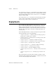
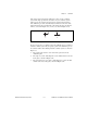
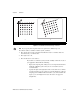
A calibration template is a user-defined grid of circular dots. As shown in
Figure 6-1, the grid has constant spacings in the x and y directions. You can
use any grid, but follow these guidelines for best results:
• The displacement in the x and y directions should be equal (dx = dy).
• The dots should cover the entire desired working area.
• The radius of the dots should be 6–10 pixels.
• The center-to-center distance between dots should range from
18 to 32 pixels, as shown in Figure 6-1.
• The minimum distance between the edges of the dots should be
6pixels,asshowninFigure6-1.
Figure 6-1. Defining a Calibration Grid
Note
You can use the calibration grid installed with IMAQ Vision at
Start»Programs»National Instruments»Vision»Documentation»Calibration Grid.
The dots have radii of 2 mm and center-to-center distances of 1 cm. Depending on your
printer, these measurements may change by a fraction of a millimeter. You can purchase
highly accurate calibration grids from optics suppliers, such as Edmund Industrial Optics.
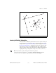
Defining a Reference Coordinate System
To express measurements in real-world units, you need to define a
coordinate system in the image of the grid. Use the
CoordinateSystem
structure to define a coordinate system by its origin, angle, and axis
direction.
1 Center-to-Center Distance 2 Center of Grid Dots 3 Distance Between Dot Edges
dy
dx
1
3
2