
User's Manual
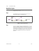
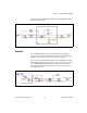
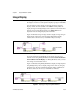
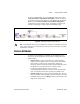
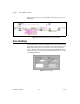
Table Of Contents
- NI-IMAQdx User Manual
- Support
- Important Information
- Contents
- Chapter 1 Introduction to NI-IMAQdx
- Chapter 2 Basic Acquisition with NI-IMAQdx
- Chapter 3 Advanced Programming with NI-IMAQdx
- Camera Attributes
- Broadcasting
- Scalable Image Size
- Trigger Modes
- Trigger Modes for IIDC Cameras
- Trigger Mode 0
- Figure 3-3. Timing Diagram for Trigger Mode 0
- Trigger Mode 1
- Figure 3-4. Timing Diagram for Trigger Mode 1
- Trigger Mode 2
- Figure 3-5. Timing Diagram for Trigger Mode 2
- Trigger Mode 3
- Figure 3-6. Timing Diagram for Trigger Mode 3
- Trigger Mode 4
- Figure 3-7. Timing Diagram for Trigger Mode 4
- Trigger Mode 5
- Figure 3-8. Timing Diagram for Trigger Mode 5
- Trigger Modes for GigE Vision Cameras
- Trigger Modes for IIDC Cameras
- Chapter 4 Using NI-IMAQdx in LabVIEW
- Chapter 5 Using NI-IMAQdx in C and .NET
- Appendix A Register-Level Programming
- Appendix B Technical Support and Professional Services
- Glossary
- Index

Chapter 4 Using NI-IMAQdx in LabVIEW
© National Instruments Corporation 4-10 NI-IMAQdx User Manual
You can use the Simple Error Handler VI, located on the Functions»
Dialog & User Interface palette, to check for errors that occur while
executing a VI. If you wire an error cluster to the Simple Error Handle VI,
the VI deciphers the error information and displays a dialog box that
describes the error. If no error occurred, the Simple Error Handler VI does
nothing. Figure 4-11 illustrates wiring an NI-IMAQdx VI to the Simple
Error Handler VI.
Figure 4-11. Error Checking Using the Simple Error Handler VI