
User's Manual
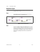
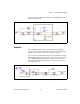
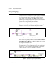
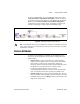
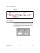
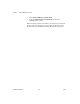
Table Of Contents
- NI-IMAQdx User Manual
- Support
- Important Information
- Contents
- Chapter 1 Introduction to NI-IMAQdx
- Chapter 2 Basic Acquisition with NI-IMAQdx
- Chapter 3 Advanced Programming with NI-IMAQdx
- Camera Attributes
- Broadcasting
- Scalable Image Size
- Trigger Modes
- Trigger Modes for IIDC Cameras
- Trigger Mode 0
- Figure 3-3. Timing Diagram for Trigger Mode 0
- Trigger Mode 1
- Figure 3-4. Timing Diagram for Trigger Mode 1
- Trigger Mode 2
- Figure 3-5. Timing Diagram for Trigger Mode 2
- Trigger Mode 3
- Figure 3-6. Timing Diagram for Trigger Mode 3
- Trigger Mode 4
- Figure 3-7. Timing Diagram for Trigger Mode 4
- Trigger Mode 5
- Figure 3-8. Timing Diagram for Trigger Mode 5
- Trigger Modes for GigE Vision Cameras
- Trigger Modes for IIDC Cameras
- Chapter 4 Using NI-IMAQdx in LabVIEW
- Chapter 5 Using NI-IMAQdx in C and .NET
- Appendix A Register-Level Programming
- Appendix B Technical Support and Professional Services
- Glossary
- Index
Chapter 4 Using NI-IMAQdx in LabVIEW
NI-IMAQdx User Manual 4-9 ni.com
Figure 4-9 shows how to set camera attributes with the property nodes in
NI-IMAQdx.
Figure 4-9. Setting Camera Attributes with Property Nodes
Error Handling
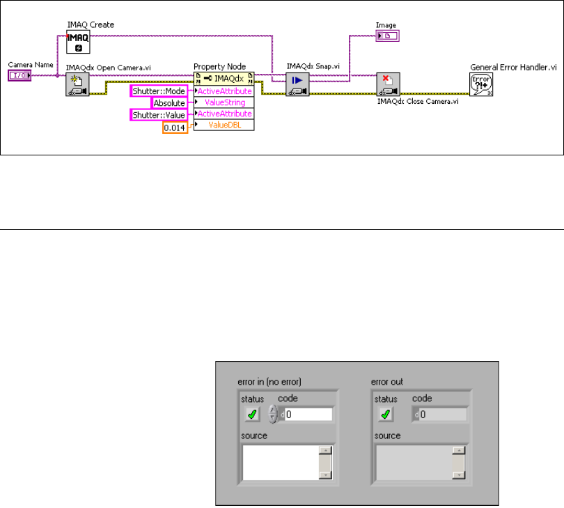
Every NI-IMAQdx VI contains an error in input cluster and an error out
output cluster. The clusters, shown in Figure 4-10, contain a Boolean value
that indicates whether an error occurred, the code for the error, and the
source or the name of the VI that returned the error. If error in indicates an
error, the VI passes the error information to error out and does not execute
any NI-IMAQdx function.
Figure 4-10. Error Clusters