
user manual

Chapter 2 Configuration and Installation
© National Instruments Corporation 2-11 NI 7350 User Manual
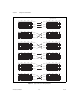
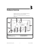
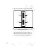
Figure 2-5. Sine Wave Motor Phasing Diagram
Table 2-2 shows the correct method of wiring a brushless motor to
the drive.
For example, if the motor has the phasing characteristics described in
Table 2-1, wire the motor lead C to the motor output 1 on the drive. You
wire the lead this way because the motor lead C calls for No Current at
0º Commutation Phase, and drive motor output 1 matches the No Current
requirement. Similarly, wire motor lead A to motor output 2 and motor
lead B to motor output 3 on the drive.
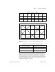
Table 2-1. Motor Phasing Diagram
Motor
Lead
0º 60º 120º 180º 240º 300º
A + + NC – – NC
B – NC + + NC –
C NC – – NC + +
Table 2-2. Correct Wiring Diagram At 0º Commutation Phase
Drive Motor Output Brushless Motor Lead State
1 No Current (NC)
2 Positive Current
3 Negative Current
0° 60° 300°240°180°120°
A
C
B
–
+
NC