
user manual

Chapter 2 Configuration and Installation
© National Instruments Corporation 2-7 NI 7350 User Manual
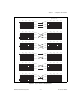
Figure 2-1. Type 1 Hall Sensor Wiring Diagrams
Type 1 Base Case
0° 180° 360° 540° 720°
0° 180° 360° 540° 720°
0° 180° 360° 540° 720°
0° 180° 360° 540° 720°
0° 180° 360° 540° 720°
0° 180° 360° 540° 720°
Sensor 1
Sensor 3
Sensor 2
Input 1
Input 2
Input 3
0° 180° 360° 540° 720°
0° 180° 360° 540° 720°
0° 180° 360° 540° 720°
0° 180° 360° 540° 720°
0° 180° 360° 540° 720°
0° 180° 360° 540° 720°
Sensor 1
Sensor 3
Sensor 2
Input 1
Input 2
Input 3
Sensor 1
Sensor 3
Sensor 2
Input 1
Input 2
Input 3
Sensor 1
Sensor 3
Sensor 2
Input 1
Input 2
Input 3
Sensor 1
Sensor 3
Sensor 2
Input 1
Input 2
Input 3
Sensor 1
Sensor 3
Sensor 2
Input 1
Input 2
Input 3