
User manual

Chapter 2 Hardware Overview
NI 5620 User Manual 2-2 ni.com
Connecting Signals
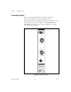
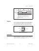
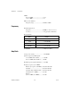
Figure 2-2 shows the NI 5620 front panel, which contains three
connectors—two SMA connectors and an SMB connector.
One of the SMA connectors, INPUT, is for attaching the analog input signal
you wish to measure. The second SMA connector, REF CLK IN, is a
50 Ω,10 MHz, AC-coupled reference input. The SMB connector, PFI1,
is for external digital triggers.
Figure 2-2. NI 5620 Front Panel
5620
64 MS/s Digitizer
INPUT
50
+20 dBm MAX
REF CLK IN
PFI 1
50
+16 dBm MAX