GPIB-PC User Manual for the IBM Personal Computer and Compatibles April 1988 Edition Part Number 320014-01 © Copyright 1984, 1994 National Instruments Corporation. All Rights Reserved.
National Instruments Corporate Headquarters 6504 Bridge Point Parkway Austin, TX 78730-5039 (512) 794-0100 Technical support fax: (800) 328-2203 (512) 794-5678 Branch Offices: Australia (03) 879 9422, Austria (0662) 435986, Belgium 02/757.00.
Limited Warranty The GPIB-PC is warranted against defects in materials and workmanship for a period of two years from the date of shipment, as evidenced by receipts or other documentation. National Instruments will, at its option, repair or replace equipment that proves to be defective during the warranty period. This warranty includes parts and labor.
National Instruments must be brought within one year after the cause of action accrues. National Instruments shall not be liable for any delay in performance due to causes beyond its reasonable control.
Preface Introduction to the GPIB The GPIB is a link, or bus, or interface system, through which interconnected electronic devices communicate. History of the GPIB The original GPIB was designed by Hewlett-Packard (where it is called the HP-IB) to connect and control programmable instruments manufactured by Hewlett-Packard.
Preface • A Getting Started with your GPIB-PC pamphlet. The pamphlet contains the directions with a minimum of explanations for installing your hardware and software in your GPIB system. • A GPIB-PC distribution diskette. The distribution diskette is part of the GPIB-PC package. It contains the DOS handler, BASICA and QuickBASIC language interfaces, and other programs. • A GPIB-PC User Manual.
Preface About the Manual This manual is written specifically for a GPIB-PC which is to be installed in an IBM Personal Computer or compatible PC which is operating under PC-DOS or MS-DOS and programmed using BASICA and QuickBASIC. With appropriate supplements to the manual, other GPIB-PC interfaces can be installed in other computers, using other programming languages. Organization of the Manual Section One - Operation of the GPIB describes the operation of the GPIB.
Preface Appendix C - Differences Between Software Revisions points out differences between revisions of the GPIB-PC handler. Appendix D - Using your Printer with the GPIB-PC gives some quick steps to connect your GPIB-PC with your printer. Appendix E - Application Notes is an application note about computerto-computer transfers. Appendix F - Customer Communication contains forms you can use to request help from National Instruments or to comment on our products and manuals.
Contents Section One - Operation of the GPIB ................................................1-1 Types of Messages......................................................................................1-1 Talkers, Listeners, and Controllers.....................................................1-1 The Controller-In-Charge and System Controller.........................1-2 GPIB Signals and Lines...........................................................................1-3 Data Lines..............................
Contents Running IBCONF ........................................................................................ 2-9 Upper and Lower Levels of IBCONF............................ 2-10 Upper Level - Device Map for Board GPIBx.................................................... 2-10 Device Map Concepts and Terms ................ 2-11 Lower Level - Device/Board Characteristics....................................................... 2-11 Device and Board Characteristics..................................
Contents Group II............................................................................................................. 3-3 IBRSP (bd,spr)...........................................................................3-3 IBCLR (bd).................................................................................. 3-4 Clearing the Device Versus Clearing the GPIB...................................................3-4 Clearing the Device .............................3-4 Clearing the GPIB......................
Contents Group VI........................................................................................................ 3-17 IBEOT (bd,v)............................................................................ 3-17 IBEOS (bd,v)............................................................................ 3-18 IBBNA (bd,"GPIBn")........................................................... 3-18 IBDMA (bd,v).......................................................................... 3-18 IBPAD (bd,v) .........
Contents IBPCT..........................................................................................................................4A-44 IBPPC ..........................................................................................................................4A-45 IBRD............................................................................................................................. 4A-47 IBRDA ..............................................................................................
Contents Byte Count................................................................................................... 5-12 Auxiliary Functions................................................................................. 5-12 SET (Select Device or Board)......................................... 5-13 HELP (Display Help Information).................................. 5-13 ! (Repeat Previous Function)........................................... 5-14 - (Turn OFF Display).......................................
Contents ESRQ(16)........................................................................................................B-6 Other Error Conditions...............................................................................B-7 Appendix C - Differences Between Software Revisions...............................................................................................C-1 Revision B and Revision C....................................................................C-1 Interrupts........................
Illustrations List of Figures Figure 1.1 - GPIB Connector and the Signal Assignment .........................1-6 Figure 1.2 - Linear Configuration .......................................................................... 1-7 Figure 1.3 - Star Configuration ...............................................................................1-8 Figure 3.1 - Multiboard GPIB System............................................................... 3-11 Figure 6.1 - Applications Monitor Popup Screen.....................
Section One - Operation of the GPIB Communication between interconnected devices is achieved by passing messages through the interface system. Types of Messages The GPIB carries two types of messages — device-dependent messages and interface messages. • Device-dependent messages, often called data or data messages, contain device-specific information such as programming instructions, measurement results, machine status, and data files. • Interface messages manage the bus itself.
Operation of the GPIB Section One The switching center (Controller) monitors the communications network (GPIB). When the Controller notices that a party (device) wants to make a call (send a data message), it connects the caller (Talker) to the receiver (Listener). The Controller usually addresses a Talker and a Listener before the Talker can send its message to the Listener. After the message is transmitted, the Controller usually unaddresses both devices.
Section One Operation of the GPIB GPIB Signals and Lines The interface system consists of 16 signal lines and 8 ground return or shield drain lines. The 16 signal lines are divided into the following three groups: • 8 data lines, • 3 handshake lines, and • 5 interface management lines. Data Lines The eight data lines, DIO1 through DIO8, carry both data and command messages. All commands and most data use the 7-bit ASCII or ISO code set, in which case the 8th bit, DIO8, is unused or used for parity.
Operation of the GPIB Section One NDAC (not data accepted) NDAC indicates when a device has or has not accepted a message byte. The line is driven by all devices when receiving commands and by Listeners when receiving data messages. DAV (data valid) DAV tells when the signals on the data lines are stable (valid) and can be accepted safely by devices. The Controller drives DAV lines when sending commands and the Talker drives DAV lines when sending data messages.
Section One Operation of the GPIB SRQ (service request) Any device can drive the SRQ line to asynchronously request service from the Controller. EOI (end or identify) The EOI line has two purposes. The Talker uses the EOI line to mark the end of a message string. The Controller uses the EOI line to tell devices to identify their response in a parallel poll.
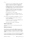
Operation of the GPIB DIO1 DIO2 DIO3 DIO4 EOI DAV NRFD NDAC IFC SRQ ATN SHIELD Section One 1 2 3 4 5 6 7 8 9 10 11 12 DIO5 DIO6 DIO7 DIO8 REN GND (TW PAIR W/DAV) GND (TW PAIR W/NRFD) GND (TW PAIR W/NDAC) GND (TW PAIR W/IFC) GND (TW PAIR W/SRQ) GND (TW PAIR W/ATN) SIGNAL GROUND 13 14 15 16 17 18 19 20 21 22 23 24 Figure 1.1 - GPIB Connector and the Signal Assignment GPIB-PC User Manual 1-6 ©National Instruments Corp.
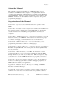
Section One Operation of the GPIB Figure 1.2 - Linear Configuration ©National Instruments Corp.
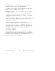
Operation of the GPIB Section One Figure 1.3 - Star Configuration GPIB-PC User Manual 1-8 ©National Instruments Corp.
Section One Operation of the GPIB Configuration Requirements To achieve the high data transfer rate that the GPIB was designed for, the physical distance between devices and the number of devices on the bus are limited. The following restrictions are typical. • A maximum separation of four meters between any two devices and an average separation of two meters over the entire bus. • A maximum total cable length of 20 meters.
Section Two - Installation and Configuration The procedures for installing your GPIB-PC depend on your model of board and your make of computer. A supplement to Section Two contains information about your interface board. Section Two A, for example, contains information about the model GPIB-PCIIA for the IBM PC and compatible computers. Installing the Hardware To install your hardware, follow the instructions in the Section Two supplement for your interface board.
Installation and Configuration Section Two • DECL.BAS - is a declaration file that contains code to be placed at the beginning of the BASICA and QuickBASIC application programs. • QBDECL.BAS - is a declaration file that contains code to be placed at the beginning of the QuickBASIC application programs. Additional Programs and Files The following additional programs and files include installation, test, and example programs: • APPMON.COM - is the applications monitor program.
Section Two • Installation and Configuration DBSAMP.BAS, BBSAMP.BAS, DQBSAMP, BIBSAMP, and DIBSAMP - are example programs for BASICA, QuickBASIC, and IBIC. The BASICA and QuickBASIC supplement of the manual, Section Four A, contains additional examples. Installing the Software The term boot disk refers to the hard disk or floppy disk that contains DOS and that is read by your computer when it is booted.
Installation and Configuration Section Two Step 2 - Run IBSTART Run IBSTART from the distribution diskette by switching to the drive containing the distribution diskette and entering: ibstart x: replacing x with the letter of the boot drive. For example, if the distribution diskette is in drive B and you have booted from drive A, enter: b: to switch to drive B. Next, enter: ibstart a: to run IBSTART.
Section Two Installation and Configuration Finally, IBSTART advises you to complete the following actions: • Run IBCONF if you must reconfigure the software; • Reboot your system to load the handler into DOS; and • Run IBTEST to test the installation of the software. Step 3 - Run IBCONF (optional) The pamphlet Getting Started with your GPIB-PC that comes with your interface board explains when you must run IBCONF to reconfigure the software.
Installation and Configuration Section Two If errors occur, check the following: • Did you read Getting Started with your GPIB-PC and make any required changes? If not, do so now. • Did you change hardware switch settings on your GPIB-PC board? If so, run IBCONF and accurately input the new settings for the board. • Are the GPIB.COM and CONFIG.SYS files installed in the root directory of your boot drive? If not, check and repeat the installation instructions.
Section Two Installation and Configuration Characteristics of the Instruments Each instrument used with the GPIB-PC has the following characteristics: • A symbolic name of each device on the GPIB (such as DEV5 or PS5010). • A GPIB-PC access board for each device (e.g., GPIB0). The access board is discussed in Device Map Concepts and Terms later in this section. • A primary and, if used, secondary address for each device. • A time limit that is to be imposed when executing certain functions.
Installation and Configuration Section Two • What DMA channel, if any, the board uses. • Whether it uses high-speed or normal timing when transmitting data to a device. With normal timing, there is a delay of at least 2 µsec after the data is placed on the GPIB before the Data Valid (DAV) line is asserted. With high-speed timing, this delay is decreased to about 500 nsec. • The Internal Clock Frequency for a PC-IIA. This is the value of the internal PC bus clock.
Section Two Installation and Configuration device is automatically terminated when END is received. No end-of-string character is recognized. • The time limit on I/O and wait function calls is approximately 10 seconds. • GPIB0 is a Model GPIB-PCII, is at base I/O address hex 02B8, and uses DMA Channel 1 and TLC Interrupt Line 7. • You must run IBCONF if you are using a GPIB-PCIIA or if you have changed the hardware switches/jumpers on any GPIB-PC from the factory settings.
Installation and Configuration Section Two IBCONF makes changes to the GPIB.COM file, which should also be in the root directory. If you want IBCONF to make changes to a different copy of GPIB.COM such as GPIB2.COM, enter the path and name of the GPIB.COM file you want modified: ibconf c:\GPIB-PC\GPIB2.COM This will have the effect of changing the parameters within the GPIB2.COM file in the GPIB-PC subdirectory. Modify only the copy of GPIB.COM created by IBSTART in your boot directory.
Section Two Installation and Configuration Device Map Concepts and Terms • Device Name - contains up to seven characters. The rules for naming devices are the same as DOS rules for naming files, except that suffixes (.xxx) are not allowed. DOS treats uppercase and lowercase letters identically. The string "PLOTTER" is treated the same as the string "plotter". For this reason, the configuration program maps all lowercase letters to uppercase.
Installation and Configuration Section Two Device and Board Characteristics Primary GPIB Address Each device and board must be assigned a unique primary address in the range hex 00 to hex 1E. A listen address is formed by adding hex 20 to the primary address; the talk address is formed by adding hex 40 to the primary address. Consequently, a primary address of hex 10 corresponds to a listen address of hex 30 and a talk address of hex 50.
Section Two Installation and Configuration This field is set to a code mnemonic which specifies the time limit as follows: Table 2.
Installation and Configuration Section Two EOS Byte Some devices can be programmed to terminate a read operation when a selected character is detected. A linefeed character (hex 0A) is a popular one. NOTE: To send the EOS character to a device in a write operation, you must explicitly include that byte in your data string. EOS Modes • Terminate a Read on EOS - Some devices send an EOS byte signaling the last byte of a data message.
Section Two Installation and Configuration Local Lockout on all Devices (Boards Only) It is desirable to place many devices in the local lockout state while they are being remotely accessed. If yes is selected, the access board will place all of its devices in local lockout state while accessing them. Disable Auto Serial Polling (Boards Only) This option allows you to disable automatic serial polls if this feature is incompatible with certain devices on the bus.
Installation and Configuration Section Two DMA Channel (Boards Only) This field appears only on computers supporting DMA capability. The GPIB-PC may use any of the three DMA channels, 1, 2, or 3, provided that another device is not already using that channel. If a DMA channel is not available, programmed I/O can be enabled by selecting NONE. Internal Clock Frequency (Boards Only) For the GPIB-PCII, this value is equal to the frequency of the PC bus signal OSC divided by 2 and rounded up.
Section Two Installation and Configuration Situations which are checked are as follows: • GPIB addressing conflict between a device and its access board; • GPIB boards not present in the host machine at the specified address; and • Timeouts disabled on a device or board. If any of these situations is encountered, you will be notified and given the option of re-entering or exiting IBCONF. To disable auto-checking, call IBCONF -E.
Installation and Configuration Section Two Using Your GPIB-PC Now that your software and hardware are installed, read Section Three for an introduction to the functions available for the GPIB-PC. The functions are described in the order that you will most likely use them. Pay special attention to Group I, Group II, and Group III.
Section Three - GPIB-PC Functions — Introduction This section introduces you to the GPIB-PC handler functions and their capabilities. They are described in the order you will most likely use them. Application environments for which the functions are designed are described. Short examples illustrate how the functions operate. Introduction to the GPIB-PC Functions The GPIB-PC functions are high-level and low-level functions that communicate with and control devices on the GPIB.
GPIB-PC Functions — Introduction Section Three Group I Group I functions may be the only functions you need for many of your instrument control applications. Group I functions are as follows: • IBRD, • IBWRT, and • IBFIND. They are suitable for your applications under the following conditions: • Communication is between the Controller (computer) and one device at a time. Messages are not broadcast to several devices at once, and devices do not talk to each other directly.
Section Three GPIB-PC Functions — Introduction IBFIND (bdname,bd) IBFIND returns a unit descriptor associated with the name of the device. When the software is installed, a description of each device is placed in an internal reference table accessible by the handler. This description includes the GPIB address, end-of-string (EOS) modes, timeout selection, and a name for the device.
GPIB-PC Functions — Introduction Section Three IBCLR (bd) IBCLR clears the device by sending to it the Selected Device Clear (SDC) and appropriate addressing commands. Clearing the Device Versus Clearing the GPIB There is a difference between clearing or initializing devices and clearing or initializing the GPIB itself.
Section Three GPIB-PC Functions — Introduction Placing a Device in Local Mode Devices must usually be placed in remote program mode before they can be programmed from the GPIB. This operation is done automatically by the handler. The IBLOC function is then used when that device must be returned to local program mode.
GPIB-PC Functions — Introduction Section Three These functions are used under the following conditions: • Program execution must proceed in parallel with GPIB I/O – often called asynchronous operation. • I/O is to or from a file rather than a memory buffer. • Controller-In-Charge authority must be transferred to another GPIB device. • The timeout value must be changed. • The handler must be reinitialized with respect to certain devices.
Section Three GPIB-PC Functions — Introduction IBTMO (bd,v) IBTMO changes the time limit in which operations with the device must complete. IBONL (bd,v) IBONL re-initializes the device and cancels any asynchronous I/O in progress. All reconfigurable software parameters, such as the time limit just discussed, are reset to their power-on values. See the discussion of software configuration in Section Two for further information on reconfigurable software parameters.
GPIB-PC Functions — Introduction Section Three Group IV The functions described previously have been device functions; that is, the bd argument referred to a device on the GPIB. This section introduces board functions, where bd refers to a specific GPIB-PC interface board in the computer.
Section Three GPIB-PC Functions — Introduction Group IV functions can be used under the following conditions: • Messages are broadcast to more than one device at a time. • Messages are sent directly from one device to another, without passing through the Controller. • GPIB lines, such as Attention (ATN), must be turned off or on in a particular fashion to ensure proper operation of a device. • Devices must be polled in parallel rather than in serial.
GPIB-PC Functions — Introduction Section Three IBFIND (bdname,bd) This is the same as the Group I function except that boards are assigned names at configuration time in the form GPIBn, where n is a board's decimal number (0, 1, 2, ...) within the computer. For instance, in a system with two GPIB boards, the first is named GPIB0 and the second GPIB1. IBCMD (bd,buf,cnt) and IBCMDA (bd,buf,cnt) Both functions use the specified board to write commands from memory to the GPIB.
Section Three GPIB-PC Functions — Introduction Boards Devices GPIB Board GPIB0 Oscilloscope SCOPE One GPIB Digital Voltmeter DVM GPIB Board GPIB1 Plotter PLTR Another GPIB Printer PRTR Figure 3.1 - Multiboard GPIB System ©National Instruments Corp.
GPIB-PC Functions — Introduction Section Three IBWRT (bd,buf,cnt) and IBWRTA (bd,buf,cnt) Both functions use the specified board to write to one or more devices that have already been addressed to listen (for example, by the IBCMD or IBCMDA function). The syntax for these low-level functions is the same as their high-level counterparts of Group I and III.
Section Three GPIB-PC Functions — Introduction IBSRE (bd,v) IBSRE uses the board to set or clear the GPIB Remote Enable (REN) line. IBGTS (bd,v) IBGTS causes the board to go from Active Controller to Standby Controller, and in so doing to turn the ATN signal off. This function is generally used to allow two external devices to talk to each other directly. The board can selectively participate in the handshake of the data transfer and hold off the handshake when the END message is detected.
GPIB-PC Functions — Introduction Section Three More About Device and Board Functions Before proceeding to the next group of functions, you will find it helpful to compare how a high-level device function can be replaced by several low-level board functions. Conducting a serial poll is a good example.
Section Three GPIB-PC Functions — Introduction Group V Group V functions are used when the GPIB-PC is not CIC. An example is a system where the computer in which the board is installed performs as an instrument, but is controlled by another device on the GPIB. Group V functions are as follows: • IBRSV, • IBLOC, • IBPPC, • IBIST, and • IBWAIT. These functions are used to: • Request service from the CIC. • Simulate a front panel "return to local" switch.
GPIB-PC Functions — Introduction Section Three IBPPC (bd,v) IBPPC locally configures or unconfigures the board for parallel polls. IBIST (bd,v) IBIST sets or clears the board's parallel poll flag (also known as the individual status bit). IBWAIT (bd,mask) This function is described in Group IV. It is included here to describe the additional events associated with noncontroller operations that the function can detect.
Section Three GPIB-PC Functions — Introduction Group VI Group VI functions are used only when the default values of the configuration parameters set during software installation need to be changed dynamically or temporarily during execution of the application program. Group VI functions are as follows: • IBEOT, • IBEOS, • IBBNA, • IBDMA, • IBPAD, • IBSAD, • IBRSC, and • IBTMO. They are used to accomplish the following actions: • Change the way I/O transmissions are terminated.
GPIB-PC Functions — Introduction Section Three IBEOS (bd,v) IBEOS assigns the end of string (EOS) character to use with subsequent IBRD and IBWRT operations. This character is compared with incoming bytes from the device and may be used to terminate a read operation. It is also compared with outgoing bytes to the device and may be used to generate the END message (EOI). IBBNA (bd,"GPIBn") IBBNA assigns board n to be the access board for device bd.
Section Four - GPIB-PC Functions — Overview This section consists of Section Four and a BASIC supplement. Section Four contains a discussion of the important characteristics common to all programming languages. The BASIC supplement lists the GPIB functions for BASICA and QuickBASIC languages. When you order a language other than BASIC, you receive a separate supplement unless your language is very similar to BASICA. Insert any new supplements in place of or in addition to Section Four A.
GPIB-PC Functions — Overview Section Four Status Word All functions return a status word containing information about the state of the GPIB and the GPIB-PC. You should test for the conditions reported in the status word to make decisions about continued processing. The status word is returned in the variable IBSTA. The status word contains 16 bits, of which 14 are meaningful. A bit value of 1 indicates the corresponding condition is in effect. A bit value of zero indicates the condition is not in effect.
Section Four ERR (db) GPIB-PC Functions — Overview ERR is set in the status word following any call that results in an error; the particular error may be determined by examining the IBERR variable. It is cleared following any call that does not result in an error. NOTE: Always check for an error condition after each call. An error made early in your application program may not become apparent until a later instruction. At that time, the error can be more difficult to locate.
GPIB-PC Functions — Overview RQS (d) Section Four RQS appears only in the status word of a device function call. Indicates that the device is requesting service. It is set in the status word whenever the hex 40 bit is asserted in the device's serial poll status byte. The serial poll which obtains the status byte may be the result of an IBRSP call, or it may be done automatically by the handler. It is cleared when the user has called IBRSP to read the serial poll status byte that caused the RQS.
Section Four GPIB-PC Functions — Overview as a Talker. It is sent either by the GPIB-PC itself or by another Controller. It is cleared whenever the GPIB-PC detects the Untalk (UNT) command, a talk address other than its own talk address, or Interface Clear (IFC). LACS (b) LACS specifies whether the GPIB-PC has been addressed as a Listener. It is set whenever the GPIB-PC detects its listen address (and secondary address, if enabled) has been sent either by the GPIB-PC itself or by another Controller.
GPIB-PC Functions — Overview Section Four Error Codes When the ERR bit is set in the status word, a GPIB error has occurred. The error code is returned in the variable IBERR. There are 14 possible error codes. Table 4.2 lists these codes, a recommended mnemonic to be associated with that type of error, and the numeric value of the code. Table 4.
Section Four GPIB-PC Functions — Overview It is also returned when an invalid unit descriptor is passed to any function call. In this case, the variable IBCNT will contain the DOS error code 6, "Invalid handle." The remedy is to be sure that IBFIND has been called and that it returned successfully. Also note that following a call to IBONL with a second argument of 0, which places bd "offline," an IBFIND is required before any subsequent calls with that device or board.
GPIB-PC Functions — Overview Section Four address to the device in the handler. For a board write, an IBCMD call is generally necessary to address devices before an IBWRT. Be sure that the proper listen address is in the IBCMD argument string and that no Unlisten (hex 3F) command follows it. ENOL may occur in situations in which the GPIB-PC is not the CIC and the Controller asserts ATN before the write call in progress has ended.
Section Four GPIB-PC Functions — Overview GPIB-PC does not have System Controller capability. The remedy is to give the GPIB-PC that capability by calling IBRSC or by using IBCONF to configure that capability into the handler. EABO (6) EABO indicates that I/O has been canceled, usually due to a timeout condition. Other causes are IBSTOP being called or the Device Clear message being received from the CIC.
GPIB-PC Functions — Overview Section Four EFSO (12) EFSO results when an IBRDF or IBWRTF call encounters a problem performing a file operation. Specifically, this error indicates the function was unable to open, create, seek, write, or close the file being accessed. The specific DOS error code for this condition is contained in IBCNT. EBUS (14) EBUS results when certain GPIB bus errors occur during device-level calls.
Section Four GPIB-PC Functions — Overview Count Variable The IBCNT variable is updated after each read, write, or command function call with the number of bytes actually transferred by the operation. Read and Write Termination The IEEE-488 specification defines two methods of identifying the last byte of device-dependent (data) messages. The two methods permit a Talker to send data messages of any length without the Listener(s) knowing in advance the number of bytes in the transmission.
GPIB-PC Functions — Overview Section Four Device Function Calls Device functions are those functions in which the unit descriptor identifies a device rather than an interface board. There are some activities common to all device functions that should be understood thoroughly. In a single board configuration in which there is only one GPIB-PC in use, when the first device function of the program is executed, the GPIB is initialized by its controlling access board with the Interface Clear (IFC) command.
Section Four GPIB-PC Functions — Overview Automatic Serial Polling If this feature is enabled, the handler automatically conducts serial polls when SRQ is asserted. The handler polls all active devices and stores each positive response, i.e., those responses that have the Request Service (RQS) or hex 40 bit set in the device status byte, in a queue associated with each device. Queues are necessary because some devices can send multiple positive status bytes back-to-back.
GPIB-PC Functions — Overview Section Four If the handler is configured with automatic serial polling enabled, this feature will be disabled after a board-level I/O function call, and resumed after a device-level I/O function call. However, if any devicelevel I/O call results in a timeout error, this feature will be disabled until the next I/O call completes.
Section Four A BASICA/QuickBASIC GPIB-PC Function Calls This section contains information for programming the GPIB-PC in BASICA and QuickBASIC, Versions 4.0 and earlier. The term BASICA, as used in this section, refers to Advanced IBM Interpretive BASIC for the IBM Personal Computer. The term QuickBASIC refers to Microsoft QuickBASIC. The programming information in this supplement can be used with all versions of BASICA and QuickBASIC unless specified otherwise.
BASICA/QuickBASIC GPIB-PC Function Calls Section Four A If information is required that is specific to three versions, this information is separated and identified by a frame with the three version numbers in the upper left corner. An example of this appears as follows: Information that is not located in a frame can be used to program the GPIB-PC in all versions of BASICA and QuickBASIC (that is, Version 4.0 and earlier).
Section Four A BASICA/QuickBASIC GPIB-PC Function Calls • QBIB2.OBJ - Version 2.0 and 3.0 without coprocessor. • QBIB_87.OBJ - Version 3.0 with coprocessor. • QBIB_87E.OBJ - Version 3.0 coprocessor emulator mode. • QBIB4.OBJ - Version 4.0 language interface.. • QBDECL4.BAS - Version 4.0 required initialization code.. The appropriate language interface depends on the version of QuickBASIC used: • DQBSAMP.BAS - A sample program using device calls. • BQBSAMP.
BASICA/QuickBASIC GPIB-PC Function Calls Section Four A You may change function and variable names defined in the code block if they conflict with names the application program is using. The substitution must be done consistently and carefully throughout. Instructions provided in this section assume that no name substitution is necessary and that the recommended names are used.
Section Four A BASICA/QuickBASIC GPIB-PC Function Calls To run your program from within the QuickBASIC editor use the QuickBASIC BUILDLIB command to add QBIB*.OBJ to your user library, and load that library when loading QuickBASIC. For example, if you are already using a library called USERLIB.EXE, add QBIB2.OBJ to it by entering: BUILDLIB USERLIB.OBJ QBIB2.OBJ; Then to run QuickBASIC enter: QB /L USERLIB.
BASICA/QuickBASIC GPIB-PC Function Calls Section Four A perform arithmetic operations on the data and want to avoid the overhead of converting the character bytes of IBRD and IBWRT into integer format and back again. IBRDI and IBWRTI are passed data in the form of an integer array, instead of a character string whose maximum length is limited to 255 bytes.
Section Four A BASICA/QuickBASIC GPIB-PC Function Calls Table 4A.
BASICA/QuickBASIC GPIB-PC Function Calls Section Four A Table 4A.
Section Four A BASICA/QuickBASIC GPIB-PC Function Calls Table 4A.2 - QuickBASIC GPIB-PC Calls (cont.
BASICA/QuickBASIC GPIB-PC Function Calls Section Four A Table 4A.
Section Four A BASICA/QuickBASIC GPIB-PC Function Calls Table 4A.
BASICA/QuickBASIC GPIB-PC Function Calls Section Four A New GPIB-PC Functions Since QuickBASIC Version 4.0 now supports true functions, the language interface has been expanded to include function versions of the existing GPIB calls. Here are some important points to be aware of: • All existing subroutines are still available via the CALL statement, and existing applications do not require any changes.
Section Four A BASICA/QuickBASIC GPIB-PC Function Calls There are a few differences between the existing subroutines and the new functions: • ILFIND returns a descriptor associated with the specified device. Use this value in all subsequent functions calls that access that device. Normal usage would resemble the following: BD% = ILFIND ("GPIB0") • ILCMD, ILCMDA, ILRD, ILRDA, and ILWRTA require a third parameter which specifies the number of bytes to transfer.
BASICA/QuickBASIC GPIB-PC Function Calls Section Four A Table 4A.4 - QuickBASIC Version 4.
Section Four A BASICA/QuickBASIC GPIB-PC Function Calls Table 4A.4 - QuickBASIC Version 4.
BASICA/QuickBASIC GPIB-PC Function Calls BASICA/QuickBASIC IBBNA Section Four A BASICA/QuickBASIC IBBNA Purpose: Change access board of device Format: CALL IBBNA (BD%,BNAME$) Remarks: BD% specifies a device. BNAME$ specifies the new access board to be used in all device calls to that device. IBBNA is needed only to alter the board assignment from its configuration setting. The IBBNA function identifies the board that will be used in subsequent device functions to access the specified device.
Section Four A BASICA/QuickBASIC GPIB-PC Function Calls BASICA/QuickBASIC IBCAC BASICA/QuickBASIC IBCAC Purpose: Become Active Controller Format: CALL IBCAC (BD%,V%) Remarks: BD% specifies an interface board. If V% is non-zero, the GPIB-PC takes control synchronously with respect to data transfer operations; otherwise, the GPIB-PC takes control immediately (and possibly asynchronously).
BASICA/QuickBASIC GPIB-PC Function Calls 2. Section Four A Take control synchronously and assert ATN following a read operation. 100 110 120 CALL IBRD (BRD0%,RD$) V% = 1 CALL IBCAC (BRD0%,V%) GPIB-PC User Manual 4A-18 ©National Instruments Corp.
Section Four A BASICA/QuickBASIC GPIB-PC Function Calls BASICA/QuickBASIC IBCLR BASICA/QuickBASIC IBCLR Purpose: Clear specified device Format: CALL IBCLR (BD%) Remarks: BD% specifies a device. The IBCLR function clears the internal or device functions of a specified device. On exit, all devices are unaddressed.
BASICA/QuickBASIC GPIB-PC Function Calls BASICA/QuickBASIC IBCMD Section Four A BASICA/QuickBASIC IBCMD Purpose: Send commands from string Format: CALL IBCMD (BD%,CMD$) Remarks: BD% specifies an interface board. CMD$ contains the commands to be sent over the GPIB. The IBCMD function is used to transmit interface messages (commands) over the GPIB.
Section Four A BASICA/QuickBASIC GPIB-PC Function Calls In the examples that follow, GPIB commands and addresses are coded as printable ASCII characters. When the values to be sent over the GPIB correspond to printable ASCII characters, this is the simplest means of specifying the values. Refer to Appendix A for conversions of numeric values to ASCII characters. Board Examples: 1.
BASICA/QuickBASIC GPIB-PC Function Calls 6. Section Four A Unaddress all Listeners and serially poll a device at talk address &H52 (ASCII R) using the Serial Poll Enable (SPE or &H18) and Serial Poll Disable (SPD or &H19) commands (the GPIB-PC listen address is &H20 or ASCII space). 100 110 120 130 140 150 160 160 170 180 190 CMD$ ="?R " + CHR$(&H18)'UNL TAD MLA SPE CALL IBCMD (BRD0%,CMD$) RD$ = SPACE$(1) ' Declare RD buffer.
Section Four A BASICA/QuickBASIC GPIB-PC Function Calls BASICA/QuickBASIC IBCMDA BASICA/QuickBASIC IBCMDA Purpose: Send commands asynchronously from string Format: CALL IBCMDA (BD%,CMD$) Remarks: BD% specifies an interface board. CMD$ contains the commands to be sent over the GPIB. The IBCMDA function is used to transmit interface messages (commands) over the GPIB.
BASICA/QuickBASIC GPIB-PC Function Calls • IBONL - Section Four A to cancel the I/O and reset the interface. The asynchronous I/O started by IBCMDA terminates for the same reasons IBCMD terminates. An ECIC error results if the GPIB-PC is not CIC. If it is not Active Controller, the GPIB-PC takes control and asserts ATN prior to sending the command bytes. It remains Active Controller afterward. The ENOL error does NOT occur if there are no Listeners. Board Example: 1.
Section Four A BASICA/QuickBASIC GPIB-PC Function Calls BASICA/QuickBASIC IBDMA BASICA/QuickBASIC IBDMA Purpose: Enable or disable DMA Format: CALL IBDMA (BD%,V%) Remarks: BD% specifies an interface board. If V% is non-zero, DMA transfers between the GPIB-PC and memory are used for read and write operations. If V% is zero, programmed I/O is used in place of DMA I/O.
BASICA/QuickBASIC GPIB-PC Function Calls BASICA/QuickBASIC IBEOS Section Four A BASICA/QuickBASIC IBEOS Purpose: Change or disable end-of-string termination mode Format: CALL IBEOS (BD%,V%) Remarks: BD% specifies a device or an interface board. V% specifies the EOS character and the data transfer termination method according to Table 4A.5. IBEOS is needed only to alter the value from its configuration setting.
Section Four A BASICA/QuickBASIC GPIB-PC Function Calls Methods B and C together determine when write operations send the END message. If Method B alone is chosen, the END message is sent automatically with the EOS byte when the low 7 bits of that byte match the low 7 bits of the EOS character. If Methods B and C are chosen, a full 8-bit comparison is used. Note that defining an EOS byte for a device or board does not cause the handler to automatically send that byte when performing IBWRTs.
BASICA/QuickBASIC GPIB-PC Function Calls Section Four A Board Examples: 1. Program the interface board BRD0% to terminate a read on detection of the linefeed character (&H0A) that is expected to be received within 200 bytes. 10 : : 100 110 120 130 140 150 160 170 180 190 2. V% = EOSV% + &H0400 CALL IBEOS (BRD0%,V%) REM Assume board has been addressed; do REM board read. RD$ = SPACE$(200) CALL IBRD (BRD0%,RD$) REM The END bit in IBSTA% is set if the REM read terminated on the EOS REM character.
Section Four A 4. Send END when the linefeed character is written for operations involving the interface board BRD0%. 10 : : 100 110 120 130 140 150 5. BASICA/QuickBASIC GPIB-PC Function Calls EOSV% = &H0A ' EOS info for IBEOS. V% = CALL REM REM WRT$ CALL EOSV% + &H0800 IBEOS (BRD0%,V%) Assume the board has been addressed; do board write.
BASICA/QuickBASIC GPIB-PC Function Calls BASICA/QuickBASIC IBEOT Section Four A BASICA/QuickBASIC IBEOT Purpose: Enable or disable END termination message on write operations Format: CALL IBEOT (BD%,V%) Remarks: BD% specifies a device or an interface board. If V% is nonzero, the END message is sent automatically with the last byte of each write operation. If V% is zero, END is not sent. IBEOT is needed only to alter the value from the configuration setting.
Section Four A BASICA/QuickBASIC GPIB-PC Function Calls Device Example: 1. Send the END message with the last byte of all subsequent writes to the device PLOTTER%. 100 110 120 130 140 V% = CALL REM REM CALL 1 ' Enable sending of EOI. IBEOT (PLOTTER%,V%) It is assumed that WRT$ contains the data to be written to the GPIB. IBWRT (PLOTTER%,WRT$) Board Examples: 1. Stop sending END with the last byte for calls directed to the interface board BRD0%. 100 110 : : 2. V% = 0 ' Disable sending of EOI.
BASICA/QuickBASIC GPIB-PC Function Calls BASICA/QuickBASIC IBFIND Section Four A BASICA/QuickBASIC IBFIND Purpose: Open device and return the unit descriptor associated with the given name Format: CALL IBFIND (BDNAME$,BD%) Remarks: BDNAME$ is a string containing a default or configured device or board name. BD% is a variable containing the unit descriptor returned by IBFIND.
Section Four A BASICA/QuickBASIC GPIB-PC Function Calls Device Example: 1. Assign the unit descriptor associated with the device named "FSDVM" (Fluke Sampling Digital Voltmeter) to the variable FSDVM%. 100 110 120 130 140 BDNAME$ = "FSDVM" ' Device name ' assigned at ' configuration time CALL IBFIND (BDNAME$,FSDVM%) IF FSDVM% < 0 GOTO 1000 ' ERROR ROUTINE Board Example: 1. Assign the unit descriptor associated with the interface board "GPIB0" to the variable BRD0%.
BASICA/QuickBASIC GPIB-PC Function Calls BASICA/QuickBASIC IBGTS Section Four A BASICA/QuickBASIC IBGTS Purpose: Go from Active Controller to Standby Format: CALL IBGTS (BD%,V%) Remarks: BD% specifies an interface board. If V% is non- zero, the GPIB-PC shadow handshakes the data transfer as an Acceptor, and when the END message is detected, the GPIB-PC enters a Not Ready For Data (NRFD) handshake holdoff state on the GPIB. If V% is zero, no shadow handshake or holdoff is done.
Section Four A BASICA/QuickBASIC GPIB-PC Function Calls Board Example: 1. Turn the ATN line off with the IBGTS function after unaddressing all Listeners with the Unlisten (UNL or ASCII ?) command, addressing a Talker at &H46 (ASCII F) and addressing a Listener at &H31 (ASCII 1) to allow the Talker to send data messages. 100 110 120 130 CMD$ CALL V% = CALL = "?F1" ' UNL MTA1 MLA2 IBCMD (BRD0%,CMD$) 1 ' Listen in continuous mode. IBGTS (BRD0%,V%) ©National Instruments Corp.
BASICA/QuickBASIC GPIB-PC Function Calls BASICA/QuickBASIC IBIST Section Four A BASICA/QuickBASIC IBIST Purpose: Set or clear individual status bit for Parallel Polls Format: CALL IBIST (BD%,V%) Remarks: BD% specifies an interface board. If V% is non-zero, the individual status bit is set. If V% is zero, the bit is cleared. The IBIST function is used when the GPIB-PC participates in a parallel poll that is conducted by another device that is the Active Controller.
Section Four A BASICA/QuickBASIC GPIB-PC Function Calls Board Examples: 1. Set the individual status bit. 100 110 2. V% = 1 ' Any non-zero value will do. CALL IBIST (BRD0%,V%) Clear the individual status bit. 100 110 V% = 0 CALL IBIST (BRD0%,V%) ©National Instruments Corp.
BASICA/QuickBASIC GPIB-PC Function Calls BASICA/QuickBASIC IBLOC Section Four A BASICA/QuickBASIC IBLOC Purpose: Go to Local Format: CALL IBLOC (BD%) Remarks: BD% specifies a device or an interface board. Unless the Remote Enable line has been unasserted with the IBSRE function, all device functions automatically place the specified device in remote program mode.
Section Four A BASICA/QuickBASIC GPIB-PC Function Calls Device Example: 1. Return the device DVM% to local state. 100 CALL IBLOC (DVM%) Board Example: 1. Return the interface board BRD0% to local state. 100 CALL IBLOC (BRD0%) ©National Instruments Corp.
BASICA/QuickBASIC GPIB-PC Function Calls BASICA/QuickBASIC IBONL Section Four A BASICA/QuickBASIC IBONL Purpose: Place the device or interface board online or offline Format: CALL IBONL (BD%,V%) Remarks: BD% specifies a device or an interface board. If V% is nonzero, the device or interface board is enabled for operation (i.e., online). If V% is zero, it is held in a reset, disabled mode (offline).
Section Four A BASICA/QuickBASIC GPIB-PC Function Calls Board Examples: 1. Disable the interface board BRD0%. 100 110 2. Enable the interface board BRD0% after taking it offline temporarily. 100 110 120 130 140 150 3. V% = 0 CALL IBONL (BRD0%,V%) BDNAME$ = "GPIB0" 'Board name assigned 'at configuration time CALL IBFIND (BDNAME$,BRD0%) REM IBONL with V% non-zero is REM automatically performed as part of REM IBFIND. Reset the configuration settings of the interface board BRD0% to their defaults.
BASICA/QuickBASIC GPIB-PC Function Calls BASICA/QuickBASIC IBPAD Section Four A BASICA/QuickBASIC IBPAD Purpose: Change Primary Address Format: CALL IBPAD (BD%,V%) Remarks: BD% specifies a device or an interface board. V% specifies the primary GPIB address of the device or interface board. IBPAD is needed only to alter the value from its configuration setting. Only the low five bits of V% are significant and they must not all be ones. Thus there are 31 valid GPIB addresses, ranging from 0 to &H1E.
Section Four A BASICA/QuickBASIC GPIB-PC Function Calls Device Example: 1. Change the primary GPIB listen and talk address of the device PLOTTER% from the configuration setting to &H2A and &H4A respectively. 100 110 V% = &HA ' Lower 5 bits of GPIB address. CALL IBPAD (PLOTTER%,V%) Board Example: 1. Change the primary GPIB listen and talk address of the interface board BRD0% from the configuration setting to &H27 and &H47 respectively. 100 110 V% = &H7 ' Lower 5 bits of GPIB address.
BASICA/QuickBASIC GPIB-PC Function Calls BASICA/QuickBASIC IBPCT Section Four A BASICA/QuickBASIC IBPCT Purpose: Pass Control Format: CALL IBPCT (BD%) Remarks: BD% specifies a device. The IBPCT function passes CIC authority to the specified device from the access board assigned to that device. The board automatically goes to Controller Idle State (CIDS). The function assumes that the device has Controller capability.
Section Four A BASICA/QuickBASIC GPIB-PC Function Calls BASICA/QuickBASIC IBPPC BASICA/QuickBASIC IBPPC Purpose: Parallel Poll Configure Format: CALL IBPPC (BD%,V%) Remarks: BD% specifies a device or an interface board. V% must be a valid parallel poll enable/disable command, or zero. When IBPPC is called and an error does not occur, the previous value of ist is stored in IBERR%.
BASICA/QuickBASIC GPIB-PC Function Calls Section Four A Which PPE and PPD messages are sent and the meaning of a particular parallel poll response are all system dependent protocol matters to be determined by you. On exit, all devices are unaddressed. Board IBPPC Function: When BD% specifies an interface board, the board itself is programmed to respond to a parallel poll by setting its local poll enable (lpe) message to the value of V%. Refer also to IBCMD, IBIST, and Table 2.1 for additional information.
Section Four A BASICA/QuickBASIC GPIB-PC Function Calls BASICA/QuickBASIC IBRD BASICA/QuickBASIC IBRD Purpose: Read data to string Format: CALL IBRD (BD%,RD$) Remarks: BD% specifies a device or an interface board. RD$ identifies the storage buffer for data bytes that are read from the GPIB. The IBRD function reads from 1 to 255 bytes of data from a GPIB device. In QuickBASIC the IBRD function reads from 1 to 32K bytes of data from a GPIB device.
BASICA/QuickBASIC GPIB-PC Function Calls Section Four A If the access board is Active Controller, the board is first placed in Standby Controller state with ATN off and remains there after the read operation is completed. Otherwise, the read operation commences immediately. An EADR error results if the board is CIC but has not been addressed to listen with the IBCMD function. An EABO error results if the board is not the CIC and is not addressed to listen within the time limit.
Section Four A BASICA/QuickBASIC GPIB-PC Function Calls Board Examples: 1. Read 56 bytes of data from a device at talk address &H4C (ASCII L) and then unaddress it (the GPIB-PC listen address is &H20 or ASCII space). 100 110 120 130 140 150 160 170 180 190 200 2. CMD$ = "? L" ' UNL MLA TAD CALL IBCMD (BRD0%,CMD$) RD$ = SPACE$(56) CALL IBRD (BRD0%,RD$) REM Check IBSTA% to see how the read REM terminated on: CMPL, END, TIMO or REM ERR. REM Data is stored in RD$. REM Unaddress the Talker and Listener.
BASICA/QuickBASIC GPIB-PC Function Calls BASICA/QuickBASIC IBRDA Section Four A BASICA/QuickBASIC IBRDA Purpose: Read data asynchronously to string Format: CALL IBRDA (BD%,RD$) Remarks: BD% specifies a device or an interface board. RD$ identifies the storage buffer for data bytes that are read from the GPIB. The IBRDA function reads from 1 to 255 bytes of data from a GPIB device. In QuickBASIC the IBRDA function reads from 1 to 32K bytes of data from a GPIB device.
Section Four A BASICA/QuickBASIC GPIB-PC Function Calls When the I/O finally completes and the CMPL bit is set in IBSTA%, the handler automatically unaddresses all devices. Board IBRDA Function: When BD% specifies an interface board, the IBRDA function attempts to read from a GPIB device that is assumed to be already properly initialized and addressed. If the board is CIC, the IBCMD function must be called prior to IBRDA to address the device to talk and the board to listen.
BASICA/QuickBASIC GPIB-PC Function Calls Section Four A Device Example: 1. Read 56 bytes of data from the device TAPE% while performing other processing. 100 110 120 130 140 150 160 170 180 190 200 210 220 230 240 REM Perform device read. RD$ = SPACE$(56) CALL IBRDA (TAPE%,RD$) MASK% = &H4100 ' TIMO CMPL REM Perform other processing here then REM wait for I/O completion or a REM timeout. CALL IBWAIT (TAPE%,MASK%) REM Check IBSTA% to see how the read REM terminated on: CMPL, END, TIMO, or REM ERR.
Section Four A BASICA/QuickBASIC GPIB-PC Function Calls Board Examples: 1. Read 56 bytes of data from a device at talk address &H4C (ASCII L) and then unaddress it (the GPIB-PC listen address is &H20 or ASCII space). 100 110 120 130 140 150 160 170 180 190 200 210 220 230 240 250 260 270 280 2. REM Perform addressing in preparation REM for board read CMD$ = "? L" ' UNL MLA TAD CALL IBCMD (BRD0%,CMD$) REM Perform board read.
BASICA/QuickBASIC GPIB-PC Function Calls BASICA/QuickBASIC IBRDF Section Four A BASICA/QuickBASIC IBRDF Purpose: Read data from GPIB into file Format: CALL IBRDF (BD%,FLNAME$) Remarks: BD% specifies a device or an interface board. FLNAME$ is the filename under which the data is stored. FLNAME$ may be up to 50 characters long, including a drive and path designation. IBRDF automatically opens the file as a binary file (as opposed to a character file). If the file does not exist, IBRDF creates it.
Section Four A BASICA/QuickBASIC GPIB-PC Function Calls The board IBRDF operation terminates on any of the following events: • Error is detected; • Time limit is exceeded; • END message is detected; • EOS character is detected (if this option is enabled); or • Device Clear (DCL) or Selected Device Clear (SDC) command is received from another device which is the CIC. After termination, IBCNT% contains the number of bytes read, modulo 65,536. Device Example: 1.
BASICA/QuickBASIC GPIB-PC Function Calls Section Four A Board Example: 1. Read data from a device at talk address &H4C (ASCII L) to the file RDGS on the current disk drive and then unaddress it (the GPIB-PC listen address is &H20 or ASCII space). 100 110 120 130 140 150 160 170 180 190 200 210 REM Perform addressing in preparation REM for board read. CMD$ = "?L " ' UNL TAD MLA CALL IBCMD (BRD0%,CMD$) REM Perform board read.
Section Four A BASICA/QuickBASIC GPIB-PC Function Calls BASICA/QuickBASIC IBRDI Purpose: BASICA/QuickBASIC IBRDI Read data to integer array Format: BASICA and QuickBASIC Version 1.0: Call IBRDI (BD%,IARR%(0),CNT%) QuickBASIC Version 2.0 and 3.0: Call IBRDI (BD%, VARPTR(IARR%(0)), CNT%) QuickBASIC Version 4.0: Call IBRDI (BD%, IARR%(), CNT%) Remarks: BD% specifies a device or an interface board. IARR% specifies an integer array into which data is read from the GPIB.
BASICA/QuickBASIC GPIB-PC Function Calls Section Four A Device Example: 1. Read 56 bytes of data from the device TAPE% and store in the integer array RD%. 100 110 120 130 140 CNT% = 56 REM Array size is equal to CNT% divided REM by 2. DIM RD% (28) CALL IBRDI (TAPE%,RD%(0),CNT%) QuickBASIC Version 2.0 or 3.0, replace line 140 with: 140 CALL IBRDI (TAPE%,VARPTR(RD%(0)),CNT%) QuickBASIC Version 4.
Section Four A BASICA/QuickBASIC GPIB-PC Function Calls Board Examples: 1. Read 56 bytes of data into the integer array RD% from a device at talk address &H4C (ASCII L) and then unaddress it (the GPIB-PC listen address is &H20 or ASCII space). 100 110 120 130 140 150 160 170 180 190 200 210 220 230 CMD$ = "? L" ' UNL MLA TAD CALL IBCMD (BRD0%,CMD$) CNT% = 56 REM Array size is equal to CNT% divided REM by 2.
BASICA/QuickBASIC GPIB-PC Function Calls BASICA/QuickBASIC IBRDIA Purpose: Section Four A BASICA/QuickBASIC IBRDIA Read data asynchronously to integer array Format: BASICA and QuickBASIC Version 1.0: Call IBRDIA (BD%,IARR%(0),CNT%) QuickBASIC Version 2 and 3: Call IBRDIA (BD%, VARPTR(IARR%(0)),CNT%) QuickBASIC Version 4: Call IBRDIA (BD%, IARR%(), CNT%) Remarks: BD% specifies a device or an interface board. IARR% specifies an integer array into which data is read asynchronously from the GPIB.
Section Four A BASICA/QuickBASIC GPIB-PC Function Calls Unlike IBRDA, IBRDIA stores the data directly into an integer array. No integer conversion is needed on the data that has been read for arithmetic operations to be performed on it. NOTE: Do not pass dynamic arrays to the asynchronous functions IBRDIA and IBWRTIA, since the QuickBASIC environment might move them around in memory during an I/O operation.
BASICA/QuickBASIC GPIB-PC Function Calls Section Four A QuickBASIC Version 4.0, replace line 150 with: 150 CALL IBRDIA (TAPE%,RD%(),CNT%) Board Examples: 1. Read 56 bytes of data into the integer array RD% from a device at talk address &H4C (ASCII L) and then unaddress it (the GPIB-PC listen address is &H20 or ASCII space). 100 110 120 130 140 150 160 170 180 190 200 210 220 230 240 250 260 270 280 290 300 310 320 330 340 REM Perform addressing in preparation REM for board read.
Section Four A BASICA/QuickBASIC GPIB-PC Function Calls QuickBASIC Version 2.0 or 3.0, replace line 190 with: 190 CALL IBRDIA (TAPE%,VARPTR(RD%(0)),CNT%) QuickBASIC Version 4.0, replace line 190 with: 190 2. CALL IBRDIA (BD%,RD%(),CNT%) To terminate the read on an end-of-string character, see IBEOS examples. ©National Instruments Corp.
BASICA/QuickBASIC GPIB-PC Function Calls BASICA/QuickBASIC IBRPP Section Four A BASICA/QuickBASIC IBRPP Purpose: Conduct a Parallel Poll Format: CALL IBRPP (BD%,PPR%) Remarks: BD% specifies a device or an interface board. PPR% identifies the variable where the parallel poll response byte is stored. Device IBRPP Function: When BD% specifies a device, all devices on its GPIB are polled in parallel using the access board of that GPIB.
Section Four A BASICA/QuickBASIC GPIB-PC Function Calls Device Example: 1. Remotely configure the device LCRMTR% to respond positively on DI03 if its individual status bit is 1, and then parallel poll all configured devices. 100 110 120 V% = %H6A CALL IBPPC (LCRMTR%,V%) CALL IBRPP (LCRMTR%,PPR%) Board Examples: 1. Remotely configure the device BRD0% at listen address &H23 (ASCII #) to respond positively on DI03 if its individual status bit is 1, and then parallel poll all configured devices.
BASICA/QuickBASIC GPIB-PC Function Calls BASICA/QuickBASIC IBRSC Section Four A BASICA/QuickBASIC IBRSC Purpose: Request or release System Control Format: CALL IBRSC (BD%,V%) Remarks: BD% specifies an interface board. If V% is non-zero, functions requiring System Controller capability are subsequently allowed. If V% is zero, functions requiring System Controller capability are disallowed.
Section Four A BASICA/QuickBASIC GPIB-PC Function Calls Board Example: 1. Request to be System Controller if the interface board BRD0% is not currently so designated. 100 110 V% = 1 ' Any non-zero value will do. CALL IBRSC (BRD0%,V%) ©National Instruments Corp.
BASICA/QuickBASIC GPIB-PC Function Calls BASICA/QuickBASIC IBRSP Section Four A BASICA/QuickBASIC IBRSP Purpose: Return serial poll byte Format: CALL IBRSP (BD%,SPR%) Remarks: BD% specifies a device. SPR% is the variable in which the poll response is stored. The IBRSP function is used to serially poll one device and obtain its status byte or to obtain a previously stored status byte. If bit 6 (the &H40 bit) of the response is set, the status response is positive, i.e.
Section Four A BASICA/QuickBASIC GPIB-PC Function Calls 3. IBCMD sends the following commands: • Untalk (UNT) and Unlisten (UNL); and • Serial Poll Disable (SPD). The interpretation of the response in SPR%, other than the RQS bit, is device-specific. For example, the polled device might set a particular bit in the response byte to indicate that it has data to transfer, and another bit to indicate a need for reprogramming. Consult the device documentation for interpretation of the response byte.
BASICA/QuickBASIC GPIB-PC Function Calls BASICA/QuickBASIC IBRSV Section Four A BASICA/QuickBASIC IBRSV Purpose: Request service and/or set or change the serial poll status byte Format: CALL IBRSV (BD%,V%) Remarks: BD% specifies an interface board. V% specifies the response or status byte the GPIB-PC provides when serially polled by another device that is the GPIB CIC. If bit 6 (the &H40 bit) is set, the GPIB-PC additionally requests service from the Controller by asserting the GPIB SRQ line.
Section Four A BASICA/QuickBASIC GPIB-PC Function Calls BASICA/QuickBASIC IBSAD BASICA/QuickBASIC IBSAD Purpose: Change or disable Secondary Address Format: CALL IBSAD (BD%,V%) Remarks: BD% specifies a device or an interface board. If V% is a number between &H6O and &H7E, that number becomes the secondary GPIB address device or interface board. If V% is &H7F or zero, secondary addressing is disabled. IBSAD is needed only to alter the value from its configuration setting.
BASICA/QuickBASIC GPIB-PC Function Calls Section Four A Device Examples: 1. Change the secondary GPIB address of the device PLOTTER% from its current value to &H6A. 100 110 2. V% = &H6A CALL IBSAD (PLOTTER%,V%) Disable secondary addressing for the device DVM%. 100 110 V% = 0 ' 0 or &H7F may be used. CALL IBSAD (DVM%,V%) Board Examples: 1. Change the secondary GPIB address of the interface board BRD0% from its current value to &H6A. 100 110 2.
Section Four A BASICA/QuickBASIC GPIB-PC Function Calls BASICA/QuickBASIC IBSIC BASICA/QuickBASIC IBSIC Purpose: Send interface clear for 100 microseconds Format: CALL IBSIC (BD%) Remarks: BD% specifies an interface board. The IBSIC function causes the GPIB-PC to assert the IFC signal for at least 100 microseconds, provided the GPIB-PC has System Controller capability.
BASICA/QuickBASIC GPIB-PC Function Calls BASICA/QuickBASIC IBSRE Section Four A BASICA/QuickBASIC IBSRE Purpose: Set or clear the Remote Enable line Format: CALL IBSRE (BD%,V%) Remarks: BD% specifies an interface board. If V% is non-zero the Remote Enable (REN) signal is asserted. If V% is zero the signal is unasserted. The IBSRE function turns the REN signal on and off. REN is used by devices to select between local and remote modes of operation. REN enables the remote mode.
Section Four A 2. BASICA/QuickBASIC GPIB-PC Function Calls To exclude the local ability of the device to return to local mode, send the Local Lockout (LLO or &H11) command or include it in the command string at 120 in Example 1. 100 110 CMD$ = CHR$(&H11) CALL IBCMD (BRD0%,CMD$) or 100 110 3. CMD$ = "#" + CHR$(&H11) CALL IBCMD (BRD0%,CMD$) Return all devices to local mode. 100 110 V% = 0 ' Set REN to false CALL IBSRE (BRD0%,V%) ©National Instruments Corp.
BASICA/QuickBASIC GPIB-PC Function Calls BASICA/QuickBASIC IBSTOP Section Four A BASICA/QuickBASIC IBSTOP Purpose: Abort asynchronous operation Format: CALL IBSTOP (BD%) Remarks: BD% specifies a device or an interface board. IBSTOP terminates any asynchronous read, write, or command operation in progress.
Section Four A BASICA/QuickBASIC GPIB-PC Function Calls Board Example: 1. Stop any asynchronous operations associated with the interface board BRD0%. 100 CALL IBSTOP (BRD0%) ©National Instruments Corp.
BASICA/QuickBASIC GPIB-PC Function Calls BASICA/QuickBASIC IBTMO Section Four A BASICA/QuickBASIC IBTMO Purpose: Change or disable time limit Format: CALL IBTMO (BD%,V%) Remarks: BD% specifies a device or an interface board.
Section Four A BASICA/QuickBASIC GPIB-PC Function Calls The IBTMO function changes the length of time that the following functions wait for the embedded I/O operation to finish or for the specified event to occur before returning with a timeout indication: • IBCMD, • IBRD, • IBRDI, • IBWRT, or • IBWRTI. The IBTMO function also changes the length of time that device functions wait for commands to be accepted.
BASICA/QuickBASIC GPIB-PC Function Calls Section Four A Device Example: 1. Change the time limit for calls involving the device TAPE% to approximately 300 msec. 100 110 V% = 10 CALL IBTMO (TAPE%,V%) Board Example: 1. Change the time limit for calls directed to the interface board BRD0% to approximately 10 msec. 100 110 V% = 7 CALL IBTMO (BRD0%,V%) GPIB-PC User Manual 4A-80 ©National Instruments Corp.
Section Four A BASICA/QuickBASIC GPIB-PC Function Calls BASICA/QuickBASIC IBTRAP BASICA/QuickBASIC IBTRAP Purpose: Alter applications monitor trap and display modes Format: CALL IBTRAP (MASK%,DISPLAY%) Remarks: MASK% specifies a bit mask with the same bit assignments as the mask used with the function IBWAIT. Each MASK% bit is set, cleared to trap, or cleared not to trap, respectively, when the corresponding bit appears in the status word after a GPIB call.
BASICA/QuickBASIC GPIB-PC Function Calls Section Four A Device Example: 1. Configure applications monitor to record and trap on SRQ or CMPL. 100 110 120 MASK% = &H1100 'SRQ or CMPL MODE% = 3 'Record and trap on CALL IBTRAP (MASK%, MODE%) GPIB-PC User Manual 4A-82 ©National Instruments Corp.
Section Four A BASICA/QuickBASIC GPIB-PC Function Calls BASICA/QuickBASIC IBTRG BASICA/QuickBASIC IBTRG Purpose: Trigger selected device Format: CALL IBTRG (BD%) Remarks: BD% specifies a device. The IBTRG function addresses and triggers the specified device, then unaddresses all devices on the GPIB.
BASICA/QuickBASIC GPIB-PC Function Calls BASICA/QuickBASIC IBWAIT Section Four A BASICA/QuickBASIC IBWAIT Purpose: Wait for selected event Format: CALL IBWAIT (BD%,MASK%) Remarks: BD% specifies a device or an interface board. MASK% is a bit mask with the same bit assignments as the status word, IBSTA%. Each MASK% bit is set or cleared to wait or not wait, respectively, for the corresponding event to occur.
Section Four A BASICA/QuickBASIC GPIB-PC Function Calls Table 4A.
BASICA/QuickBASIC GPIB-PC Function Calls Section Four A Device Example: 1. Wait indefinitely for the device LOGGER% to request service. 100 110 MASK% = &H800 CALL IBWAIT (LOGGER%,MASK%) ' RQS Board Examples: 1. Wait for a service request or a timeout. 100 110 120 130 2. Update the current status for IBSTA%. 100 110 3. MASK% = 0 CALL IBWAIT (BD%,MASK%) Wait indefinitely until control is passed from another CIC. 100 110 4.
Section Four A BASICA/QuickBASIC GPIB-PC Function Calls BASICA/QuickBASIC IBWRT BASICA/QuickBASIC IBWRT Purpose: Write data from string Format: CALL IBWRT (BD%,WRT$) Remarks: BD% specifies a device or an interface board. WRT$ contains the data to be sent over the GPIB. In BASICA, the IBWRT function writes from 1 to 255 bytes of data to a GPIB device. In QuickBASIC, the IBWRT function writes from 1 to 32K bytes of data to a GPIB device.
BASICA/QuickBASIC GPIB-PC Function Calls Section Four A If the access board is Active Controller, the board is first placed in Standby Controller state with ATN off and remains there after the write operation is completed. Otherwise, the write operation commences immediately. An EADR error results if the board is CIC but has not been addressed to talk with the IBCMD function. An EABO error results if the board is not the CIC and is not addressed to talk within the time limit.
Section Four A BASICA/QuickBASIC GPIB-PC Function Calls Board Example: 1. Write 10 instruction bytes to a device at listen address &H2F (ASCII /) and then unaddress it (the GPIB-PC talk address is &H40 or ASCII @). 100 110 120 130 140 150 160 170 180 REM CMD$ CALL REM WRT$ CALL REM CMD$ CALL Perform addressing. = "?@/" ' UNL MTA LAD IBCMD (BRD0%,CMD$) Perform board write. = "F3R1X5P2G0" IBWRT (BRD0%,WRT$) Unaddress the Talker and Listener.
BASICA/QuickBASIC GPIB-PC Function Calls BASICA/QuickBASIC IBWRTA Section Four A BASICA/QuickBASIC IBWRTA Purpose: Write data asynchronously from string Format: CALL IBWRTA (BD%,WRT$) Remarks: BD% specifies a device or an interface board. WRT$ contains the data to be sent over the GPIB. This is a special case of the IBWRTA function which in BASICA writes a maximum of 255 bytes from a character string to the GPIB.
Section Four A BASICA/QuickBASIC GPIB-PC Function Calls When the device IBWRTA function returns, IBSTA% holds the latest device status and IBERR% is the first error detected, if the ERR bit in IBSTA% is set. When the I/O finally completes and the CMPL bit is set in IBSTA%, the handler automatically unaddresses all devices. Board IBWRTA Function: When BD% specifies an interface board, the IBWRTA function attempts to write to a GPIB device that is assumed to be already properly initialized and addressed.
BASICA/QuickBASIC GPIB-PC Function Calls Section Four A Device Example: 1. Write 10 instruction bytes to the device DVM% while performing other processing. 100 110 120 130 140 150 160 170 180 190 200 210 WRT$ = "F3R1X5P2G0" CALL IBWRTA (DVM%,WRT$) MASK% = &H4100 'TIMO CMPL REM Perform other processing here then REM wait for I/O completion or a REM timeout. CALL IBWAIT (DVM%,MASK%) REM Check IBSTA% to see how the write REM terminated on: CMPL, END, TIMO, or REM ERR.
Section Four A BASICA/QuickBASIC GPIB-PC Function Calls BASICA/QuickBASIC IBWRTF BASICA/QuickBASIC IBWRTF Purpose: Write data from file Format: CALL IBWRTF (BD%,FLNAME$) Remarks: BD% specifies a device or an interface board. FLNAME$ indicates the filename from which the data is written to the GPIB. FLNAME$ may be up to 50 characters long, including a drive and path designation. IBWRTF automatically opens the file. On exit, IBWRTF closes the file.
BASICA/QuickBASIC GPIB-PC Function Calls Section Four A The board IBWRTF operation terminates on any of the following events: • All bytes sent; • Error is detected; • Time limit is exceeded; or • Device Clear (DCL) or Selected Device Clear (SDC) command is received from another device which is the CIC. After termination, IBCNT% contains the number of bytes written, modulo 65,536. Device Example: 1. Write data to the device RDR% from the file Y.DAT on the current disk drive. 100 110 FLNAME$ = "Y.
Section Four A BASICA/QuickBASIC GPIB-PC Function Calls BASICA/QuickBASIC IBWRTI Purpose: BASICA/QuickBASIC IBWRTI Write data from integer array Format: BASICA and QuickBASIC Version 1.0: Call IBWRTI (BD%,IARR%(0),CNT%) QuickBASIC Version 2.0 and 3.0: Call IBWRTI (BD%, VARPTR(IARR%(0)), CNT%) QuickBASIC Version 4.0: Call IBWRTI (BD%, IARR%(), CNT%) Remarks: BD% specifies a device or an interface board. IARR% is an integer array from which data is written to the GPIB.
BASICA/QuickBASIC GPIB-PC Function Calls Section Four A Device Examples: 1. Write 10 instruction bytes from the integer array WRT% to the device DVM%. 100 110 120 130 140 150 160 170 DIM WRT%(4) WRT%(0) = ASC("F") + ASC("3") * WRT%(1) = ASC("R") + ASC("1") * WRT%(2) = ASC("X") + ASC("5") * WRT%(3) = ASC("P") + ASC("2") * WRT%(4) = ASC("G") + ASC("0") * CNT% = 10 CALL IBWRTI (DVM%,WRT%(0),CNT%) 256 256 256 256 256 QuickBASIC Version 2.0 and 3.
Section Four A BASICA/QuickBASIC GPIB-PC Function Calls Board Example: 1. Write 10 instruction bytes from the integer array WRT% to a device at listen address &H2F (ASCII /) and then unaddress it (the GPIB-PC talk address is &H40 or ASCII @). 100 120 130 140 150 160 170 180 190 200 210 220 230 240 250 260 REM Perform addressing. CMD$ = "?@/" ' UNL MTA LAD CALL IBCMD (BRD0%,CMD$) REM Perform board write.
BASICA/QuickBASIC GPIB-PC Function Calls BASICA/QuickBASIC IBWRTIA Purpose: Section Four A BASICA/QuickBASIC IBWRTIA Write data asynchronously from integer array Format: BASICA and QuickBASIC Version 1.0: Call IBWRTIA (BD%,IARR%(0),CNT%) QuickBASIC Version 2.0 and 3.0: Call IBWRTIA (BD%, VARPTR(IARR%(0)), CNT%) QuickBASIC Version 4.0: Call IBWRTIA (BD%, IARR%(), CNT%) Remarks: BD% specifies a device or an interface board. IARR% is an array from which integer data is written.
Section Four A BASICA/QuickBASIC GPIB-PC Function Calls NOTE: Do not pass dynamic arrays to the asynchronous functions IBRDIA and IBWRTIA, since the QuickBASIC environment might move them around in memory during an I/O operation. Device Example: 1. Write 10 instruction bytes from integer array to the device DVM% while performing other processing.
BASICA/QuickBASIC GPIB-PC Function Calls Section Four A Board Example: 1. Write 10 instruction bytes from the integer array WRT% to a device at listen address &H2F (ASCII /) and then unaddress it (the GPIB-PC talk address is &H40 or ASCII @). 100 110 120 130 140 150 160 170 180 190 200 210 220 230 240 260 270 280 290 REM Perform addressing. CMD$ = "?@/" ' UNL MTA LAD CALL IBCMD (BRD0%,CMD$) REM Perform board write.
Section Four A BASICA/QuickBASIC GPIB-PC Function Calls BASICA/QuickBASIC GPIB Programming Examples This section illustrates the programming steps that could be used to program a representative IEEE-488 instrument from your personal computer using the GPIB-PC handler functions. The applications are written in BASICA and QuickBASIC. The target instrument is a digital voltmeter (DVM). This instrument is otherwise unspecified (that is, it is not a DVM manufactured by any particular manufacturer).
BASICA/QuickBASIC GPIB-PC Function Calls 6. Section Four A c. Serially poll the DVM to determine if the measured data is valid (status byte = &HC0) or if a fault condition exists (the &H40 bit and another bit of the status byte, other than &H80, are set). d. If the data is valid, read 16 bytes from the DVM. End the session. The example programs that follow are based on these assumptions: • The GPIB-PC is the designated System Active Controller of the GPIB.
Section Four A BASICA/QuickBASIC GPIB-PC Function Calls BASICA Example Program - Device BASICA - Using device function calls. 100 105 110 120 125 130 140 145 150 155 160 170 180 185 190 195 200 210 215 220 230 240 250 255 260 270 280 290 295 300 310 320 330 340 350 355 360 370 380 390 400 410 REM You must merge this code with DECL.BAS. REM REM Assign a unique identifier to device and REM store in variable DVM%. REM BDNAME$ = "DVM" CALL IBFIND (BDNAME$,DVM%) REM REM Check for error on IBFIND call.
BASICA/QuickBASIC GPIB-PC Function Calls 415 420 430 440 450 460 470 475 480 490 500 510 520 525 530 540 550 560 570 575 580 585 590 Section Four A REM CALL IBRSP (DVM%,SPR%) IF IBSTA% < 0 THEN GOTO 3000 REM REM Now test the status byte (SPR%). REM If SPR% is &HC0, the DVM has valid data REM to send; otherwise, it has a fault REM condition to report. REM IF SPR% <> &HC0 THEN GOTO 4000 REM REM If the data is valid, read the REM measurement.
Section Four A BASICA/QuickBASIC GPIB-PC Function Calls BASICA Example Program - Board BASICA - Using board function calls 100 105 110 120 125 130 140 145 150 153 155 160 165 170 175 180 190 200 215 220 230 240 245 250 260 270 280 290 300 310 320 330 345 350 360 370 380 390 400 405 410 420 REM You must merge this code with DECL.BAS. REM REM Assign a unique identifier to board 0 and REM store in the variable BRD0%. REM BDNAME$ = "GPIB0" CALL IBFIND (BDNAME$,BRD0%) REM REM Check for error on IBFIND call.
BASICA/QuickBASIC GPIB-PC Function Calls 430 440 450 455 460 470 480 490 500 510 515 520 530 540 550 560 570 580 590 600 610 615 620 630 640 650 660 670 680 690 695 700 710 720 730 731 732 734 735 736 738 740 750 760 765 770 780 REM REM REM REM Section Four A Send the GET message to trigger a measurement reading.
Section Four A BASICA/QuickBASIC GPIB-PC Function Calls 790 800 810 815 820 825 830 840 850 860 870 880 885 890 900 910 REM REM Since the DVM and GPIB-PC are still REM addressed to talk and listen, the REM measurement can be read REM as follows. REM RD$ = SPACE$(16) : CALL IBRD (BRD0%,RD$) IF IBSTA% < 0 THEN GOTO 3000 REM REM To close out a programming sequence, send REM IFC to initialize the bus and call the REM IBONL function to place the GPIB-PC REM offline.
BASICA/QuickBASIC GPIB-PC Function Calls Section Four A QuickBASIC Example Program - Device QuickBASIC - Using device function calls. COMMON SHARED IBSTA%, IBERR%, IBCNT% REM Assign a unique identifier to device REM and store in variable DVM%. REM BDNAME$ = "DVM" CALL IBFIND (BDNAME$,DVM%) REM REM Check for error on IBFIND call. REM IF DVM% < 0 THEN GOSUB FIND-ERROR: REM REM Clear the device. REM CALL IBCLR (DVM%) REM REM Check for an error on each GPIB call REM to be safe.
Section Four A BASICA/QuickBASIC GPIB-PC Function Calls CALL IBRSP (DVM%,SPR%) IF IBSTA% < 0 THEN GOSUB GPIB-ERROR: REM REM Now test the status byte (SPR%). REM If SPR% is &HC0, the DVM has valid REM data to send; otherwise, it has a REM fault condition to report. REM IF SPR% <> &HC0 THEN GOSUB DEVICE-ERROR: REM REM If the data is valid, read the REM measurement.
BASICA/QuickBASIC GPIB-PC Function Calls Section Four A DEVICE-ERROR: REM A routine at this location would analyze REM the fault code returned in the DVM's status REM byte and take appropriate action. PRINT "DVM ERROR" : STOP END GPIB-PC User Manual 4A-110 ©National Instruments Corp.
Section Four A BASICA/QuickBASIC GPIB-PC Function Calls QuickBASIC Example Program - Board QuickBASIC - Using board function calls. COMMON SHARED IBSTA%, IBERR%, IBCNT% REM REM Assign a unique identified to board 0 and REM store in variable BRD0%. REM BDNAME$ = "GPIB0" CALL IBFIND (BDNAME$,BRD0%) REM REM Check for error on IBFIND call. REM IF BRD0% < 0 THEN GOSUB FIND-ERROR: REM REM Send the Interface Clear (IFC) message to REM all devices.
BASICA/QuickBASIC GPIB-PC Function Calls Section Four A IF IBSTA% < 0 THEN GOSUB GPIB-ERROR: REM REM Send the GET message to trigger a REM measurement reading. REM CMD$ = CHR$(&H8) : CALL IBCMD (BRD0%,CMD$) IF IBSTA% < 0 THEN GOSUB GPIB-ERROR: REM REM Wait for the DVM to set SRQ or for a REM timeout; if the current time limit REM is too short, use IBTMO to change it.
Section Four A BASICA/QuickBASIC GPIB-PC Function Calls CMD$ = CHR$(&H19) : CALL IBCMD (BRD0%,CMD$) IF IBSTA% < 0 THEN GOSUB GPIB-ERROR: REM REM Since the DVM and GPIB-PC are REM still addressed to talk and listen, REM the measurement can be read as follows. REM RD$ = SPACE$(16) : CALL IBRD (BRD0%,RD$) IF IBSTA% < 0 THEN GOSUB GPIB-ERROR: REM REM To close out a programming sequence, REM send IFC to initialize the bus and REM call the IBONL function to place the REM GPIB-PC offline.
Section Five - IBIC The IEEE-488 Bus Interactive Control program (IBIC) allows you to control and communicate with the GPIB through functions you enter at the keyboard. This feature helps you establish communication with the device, troubleshoot problems, and develop the application. IBIC functions include most of the GPIB-PC functions described in Sections Three and Four, plus auxiliary functions used only by IBIC.
IBIC Section Five Running IBIC The IBIC program, IBIC.EXE, is an executable file that was copied from the distribution diskette to a subdirectory called GPIB-PC when you ran IBSTART at installation. To run IBIC, change directory to C:\GPIB-PC and enter: C:\GPIB-PC> ibic National Instruments Interface Bus Interactive Control Copyright (c) 1984 National Instru All Rights Reserved Program (IBIC) ments, Inc. Type "help" for help.
Section Five IBIC Using HELP The HELP function gives on-line information about IBIC and the functions available within the environment. This facility provides a quick reference for checking the syntax and function of the GPIB call. Using IBFIND To execute any GPIB function, you must first use IBFIND to open the device or board you wish to use. When the device or board is opened, the symbolic name of that device or board is added to the prompt.
IBIC Section Five Using IBWRT The IBWRT command sends data from one GPIB device to another. For example, to send a data string from the computer to a device called dev1, the following command would suffice: Example: dev1: ibwrt "F3R5T1" [0100] (cmpl) count: 6 This command sends the string "F3R5T1" to device called dev1. The returned Status Word [0100] indicates a successful I/O completion, while the Byte Count indicates that all six characters were sent from the computer and received by the device.
Section Five IBIC This command receives data from the device and displays it on the screen in hexadecimal format, and provides its ASCII equivalent, along with information about the data transfer such as the Status Word and the Byte Count. How to Exit IBIC Typing e or q will return you to DOS. Important Programming Note Some GPIB instruments require special termination characters or End of String (EOS) characters to indicate to the device the end of transmission.
IBIC Section Five Using SET Use IBFIND to open each device or board. Once the device or board is opened, use the auxiliary function SET to select which opened device or board to access. SET changes the prompt to the new symbolic name. Example: dev1: set plotter plotter: This example assumes that IBCONF was used to give a device the name plotter. The following example summarizes the use of IBFIND and SET in a typical program.
Section Five IBIC IBIC Functions and Syntax IBIC displays the following information about each function call immediately after that call: • IBRD and IBRDA data messages are displayed on the screen in hex and ASCII formats. • The global variables IBSTA, IBCNT, and IBERR are displayed on the screen. IBIC and programming languages of Section Four differ in the syntax of the function call. These differences are shown in Table 5.1.
IBIC Section Five Other IBIC Functions and Syntax Table 5.1 summarizes the GPIB-PC functions and syntax when called from IBIC. Syntax rules for IBIC are explained in the table notes. Consult Section Four for detailed function descriptions and for syntax rules of the programming language you will use. Table 5.
Section Five IBIC Table 5.
IBIC Section Five characters into the string as shown in the following string: F3R5T1\r\n. Since the carriage return can be represented equally well in hex, xD and r are equivalent strings. 5. bdname is the symbolic name of the new device or board; for example, ibfind dev1 or set gpib0. 6. v is the number of bytes to read. 7. flname is the DOS pathname of the file to be read or written, e.g., \test\meter or printr.buf. 8. mask is a hex, octal, or decimal integer (see note 3) or a mask bit mnemonic.
Section Five IBIC Table 5.2 - Status Word Layout Mnemonics Bit 15 14 13 12 11 Hex Pos.
IBIC Section Five Byte Count When an I/O function completes, IBIC displays the actual number of bytes sent or received, regardless of the existence of an error condition. Auxiliary Functions Table 5.3 summarizes the auxiliary functions that IBIC supports. Table 5.
Section Five 6. IBIC string consists of a list of ASCII characters, octal or hex bytes, or special symbols. The entire sequence of characters must be enclosed in quotes. An octal byte consists of a backslash character followed by the octal value. For example, octal 40 would be represented by 040. A hex byte consists of a backslash character and a character x followed by the hex value. For example, hex 40 would be represented by x40.
IBIC Section Five ! (Repeat Previous Function) The ! function causes the most recent function executed to be repeated. Example: Screen Image gpib0: ibsic Clear cic atn ) gpib0: ! [130] ( cmpl cic atn ) gpib0: ! [130] ( cmpl cic atn ) Comments Send Interface [130] ( cmpl Repeat ibsic Repeat ibsic again - (Turn OFF Display) The - function causes the GPIB-PC function output NOT to be displayed on the screen.
Section Five IBIC + (Turn ON Display) The + function causes the display to be restored. The following example shows how the - and + functions are used. Twenty-four consecutive letters of the alphabet are read from a device using three IBRD calls. Example: ibrd 8 dev1: [4100] (end cmpl) COUNT: 8 61 62 63 64 65 66 67 68 a b c d e f g h q r s t u v w x dev1: dev1: ibrd 8 dev1: + dev1: ibrd 8 [4100] (end cmpl) COUNT: 8 71 72 73 74 75 76 77 78 ©National Instruments Corp.
IBIC Section Five n* (Repeat Function n Times) The n* function repeats the execution of the specified function n times, where n is an integer. In the following example, the message Hello will be sent to the printer five times. Example: printer: 5*ibwrt "Hello" The function name can be replaced with the ! function. Thus, if this example is done the following way, the word Hello will be sent 20 more times, then 10 more times.
Section Five IBIC $ (Execute Indirect File) In the $ function, an indirect file is a text file that contains IBIC functions. It is similar to a DOS batch file and is created the same way. This function reads the specified indirect file and executes the IBIC functions in sequence as if they were entered in that order from the keyboard. Example: gpib0: $ usrfile executes the IBIC functions listed in the file usrfile, and gpib0: 3*$ usrfile repeats that operation three times.
IBIC Section Five PRINT (Display the ASCII String) The PRINT function can be used to echo a string to the screen. Example: dev1: print "hello" hello dev1: print "and\r\n\x67\x6f\x6f\x64\x62\x79\x65" and goodbye PRINT can be used to display comments from indirect files. The print strings will appear even if the display is suppressed with the - function. The second PRINT example illustrates the use of hex values in IBIC strings.
Section Five IBIC IBIC Sample Programs Refer to Section Four A, BASICA/QuickBASIC GPIB Programming Examples, for a description of the programming steps that could be used to program a representative IEEE-488 instrument from your personal computer using the GPIB-PC handler functions. The applications are written using IBIC commands. Device Function Calls To communicate with a device, first "find" the device name which was given to the device in the IBCONF program.
IBIC Section Five Write the function, range, and trigger source instructions to the DVM. Example: DVM: ibwrt "F3R7T3" [0100] (cmpl) count: 6 Trigger the device. Example: DVM: ibtrg [0100] (cmpl) Wait for the DVM to request service or for a timeout; if the current timeout limit is too short, use ibtmo to change it. Example: DVM: ibwait (TIMO RQS) [800] (rqs) GPIB-PC User Manual 5-20 ©National Instruments Corp.
Section Five IBIC Read the serial poll status byte. This serial poll status byte will vary depending on the device used. Example: DVM: ibrsp [0100] (cmpl) Poll: 0x40 (decimal : 32) The read command displays the data on the screen both in hex values and their ASCII equivalents. Example: DVM: ibrd 18 [0100] (cmpl) count: 18 4E 44 43 56 20 30 30 30 N D C V 2E 30 30 34 37 45 28 30 . 0 0 4 7 OA OA ©National Instruments Corp.
IBIC Section Five Return to DOS. Example: DVM: e Board Function Calls Make the interface board the current board. Example: :ibfind gpib0 GPIB0: Send the interface clear message (IFC) to all devices. This clears the bus and asserts attention (ATN) on the bus. The user should check for ERR after each GPIB function call to be safe. Example: GPIB0: ibsic [0130] (cmpl cic atn) GPIB-PC User Manual 5-22 ©National Instruments Corp.
Section Five IBIC Turn on the remote enable signal (REN). Example: GPIB0: ibsre 1 [0130] (cmpl cic atn) previous value: 0 Set up the addressing for the device to listen and the computer to talk. The question mark (?) and underscore (_) characters represent the unlisten (UNL) and untalk (UNT) commands, respectively. These must be sent first in every IBCMD function to reset the bus addressing. The @ character represents the GPIB-PC board's talk address.
IBIC Section Five Write the function, range, and trigger source instructions to the DVM. Be sure an error has not occurred before proceeding with the sample program. Example: GPIB0: ibwrt "F3R7T3" [01A8] (cmpl lok cic tacs) count: 6 Send the group execute trigger message (GET) to trigger a measurement reading. The GET message is represented by the hex value 8.
Section Five IBIC GPIB0: ibwait (TIMO SRQI) [4188] (timo cmpl lok cic atn tacs ) Set up the device for a serial poll. The ? and _ represent the unlisten (UNL) and untalk (UNT) characters, respectively, and reset the address. The hex value 18 represents the serial poll enable function, while the A represents the device's talk address. Example: GPIB: ibcmd "?_\x18A" Read the status byte. The status byte returned may vary depending on the device used.
IBIC Section Five Example: GPIB0: ibcmd "\x19" [01F4] (cmpl lok rem cic atn lacs) count: 1 Since the DVM and the GPIB-PC are still addressed to talk and to listen, the measurement can be read. Example: GPIB0: ibrd 20 [01E4] (cmpl lok rem cic lacs) 0D 0A 4E 44 43 56 2D 30• • N D C 30 30 2E 30 30 34 37 450 0 . 0 0 2B 30 0D 0A + 0 • • V - 0 4 7 E To close out a programming sequence, send the interface clear message (IFC) to initialize the bus.
Section Five IBIC Example: GPIB0: e ©National Instruments Corp.
Section Six - Applications Monitor The applications monitor is a memory resident program which is useful in debugging sequences of GPIB calls from within your application. The monitor provides the capability to trap on return from GPIB driver calls, allowing you to inspect function arguments, buffers, return values, GPIB global variables, and other pertinent data.
IBIC Section Six In many cases, use of the applications monitor allows you to omit explicit error-checking code from the application. If a program is expected to run without errors, trapping on errors will cause the monitor to be invoked only if an error occurs during a GPIB call. You may then take the action necessary to fix the problem. Currently, the applications monitor is only supported by the Revision C.5.1 and later versions of the GPIB Rev. C handler.
Section Six IBIC the desired combination of the flags which are listed on the following pages.
IBIC Section Six Select only one monitor flag: -off turns the monitor off. No recording or trapping occurs. -rec instructs the monitor to record all GPIB handler calls but no trapping occurs. -dis instructs the monitor to record all GPIB handler calls and display whenever a trap condition exists. Omitting either the mask or the monitor flags will leave its current configuration unchanged. Invoking IBTRAP without any flags will display the valid flags and their current state.
Section Six IBIC Applications Monitor Options When displayed, the applications monitor allows you to view the parameters of the current GPIB call, change the display and trap modes, and scan the GPIB session summary. The monitor displays the following information pertinent to the current GPIB call: Device symbolic device name. Function GPIB-PC function mnemonic and description. Value for functions that have a number as their second parameter, this contains its value, otherwise it is undefined.
IBIC Section Six NOTE: All numbers are displayed in hexadecimal. Also, the monitor is unable to record IBFIND or IBTRAP calls. GPIB-PC User Manual 6-6 ©National Instruments Corp.
Section Six IBIC Main Commands When the main monitor screen is displayed, the following command keys are available: F1 continue executing applications program F2 display session summary F5 configure trap mask F6 configure monitor mode F7 hide/show monitor F8 clear session summary buffer F10 display command key list Cursor Up scroll buffer up one character Cursor Down scroll buffer down one character Page Up scroll buffer up one page Page Down scroll buffer down one page Home scroll
IBIC Section Six Session Summary Screen This session summary can be viewed by pressing F2.
Section Six IBIC Hiding and Showing the Monitor Pressing F7 will hide the monitor and restore the contents of the screen. This allows you to view program output written to the screen while active within the monitor. Pressing F7 again will restore the monitor. ©National Instruments Corp.
Appendix A - Multiline Interface Messages The following tables are multiline interface messages (sent and received with ATN TRUE). The subsequent pages contain an interface message reference list, which describes the mnemonics and messages which correspond to the interface functions. ©National Instruments Corp.
Multiline Interface Messages Appendix A Multiline Interface Messages Hex O c t D e c ASCII 00 01 02 03 04 05 06 07 000 001 002 003 004 005 006 007 0 1 2 3 4 5 6 7 NUL SOH STX ETX EOT ENQ ACK BEL 08 09 0A 0B 0C 0D 0E 0F 010 011 012 013 014 015 016 017 8 9 10 11 12 13 14 15 BS HT LF VT FF CR SO SI 10 11 12 13 14 15 16 17 020 021 022 023 024 025 026 027 16 17 18 19 20 21 22 23 DLE DC1 DC2 DC3 DC4 NAK SYN ETB 18 19 1A 1B 1C 1D 1E 1F 030 031 032 033 034 035 036 037 24 25 26 27 28 29 30 31 CAN
Appendix A Multiline Interface Messages Multiline Interface Messages Hex O c t D e c ASCII Msg Hex O c t D e c ASCII Msg 40 41 42 43 44 45 46 47 100 101 102 103 104 105 106 107 64 65 66 67 68 69 70 71 @ A B C D E F G MTA0 MTA1 MTA2 MTA3 MTA4 MTA5 MTA6 MTA7 60 61 62 63 64 65 66 67 140 141 142 143 144 145 146 147 96 97 98 99 100 101 102 103 ` a b c d e f g MSA0,PPE MSA1,PPE MSA2,PPE MSA3,PPE MSA4,PPE MSA5,PPE MSA6,PPE MSA7,PPE 48 49 4A 4B 4C 4D 4E 4F 110 111 112 113 114 115 116 117 72 73 7
Multiline Interface Messages Appendix A Interface Message Reference List Mnemonic Message Interface Function(s) LOCAL MESSAGES RECEIVED (by interface functions) gts ist lon [lpe] ltn lun nba pon rdy rpp rsc rsv rtl sic sre tca tcs ton go to standby individual status qualifier listen only local poll enable listen local unlisten new byte available power on ready request parallel poll request system control request service return to local send interface clear send remote enable take control asynchronousl
Appendix A Multiline Interface Messages Interface Message Reference List (Continued) Mnemonic Message Interface Function(s) REMOTE MESSAGES RECEIVED REN RFD RQS [SDC] SPD SPE SRQ STB TCT or [TCT] UNL remote enable ready for data request service selected device clear serial poll disable serial poll enable service request status byte take control unlisten (continued) RL SH (via L, LE) DC T, TE T, TE (via C) (via L, LE) C L, LE REMOTE MESSAGES SENT ATN DAB DAC DAV DCL END GET GTL IDY IFC LLO MLA or [ML
Appendix B - Common Errors and Their Solutions Some errors occur more frequently than others. These common errors and their solutions are listed in this appendix, according to the error code that was returned from the function as indicated by IBERR. A full explanation of all possible errors is in Section Four. Later in this appendix are descriptions of error situations that do not return an error code. EDVR(0) Error Condition: DOS error (see IBCNT for DOS error code). Solutions: • Check that GPIB.
Common Errors and Their Solutions Appendix B ENOL(2) Error Condition: Write function detected no Listeners. Solutions: • Check that the device is powered on, and also that at least twothirds of the devices on the GPIB are turned on. • Inspect the interconnecting cable to see that the devices are attached and that the connectors are seated properly. • Check the switches or control panel of the device and make sure its GPIB address is what you think it is.
Appendix B Common Errors and Their Solutions EADR(3) Error Condition: GPIB-PC (GPIB0 or GPIB1) is not addressed correctly. Solutions: • Use IBCMD to send the appropriate Talk or Listen address before attempting an IBWRT or IBRD. • If calling IBGTS with the shadow handshake feature, call IBCMD to ensure that the GPIB ATN line is asserted. EARG(4) Error Condition: Invalid argument to function call. Solutions: • • Errors received from IBIC: - Verify syntax in Section Five.
Common Errors and Their Solutions Appendix B ESAC(5) Error Condition: GPIB-PC not System Controller as required. Solutions: • Run IBCONF and make sure the board (GPIB0 or GPIB1) is configured to be System Controller. • Issue a board IBRSC function call with a value of 1 to request System Control. EABO(6) Error Condition: I/O operation aborted. Solutions: • Check that the device is powered on. • Verify proper cable connections.
Appendix B Common Errors and Their Solutions ENEB(7) Error Condition: Non-existent GPIB-PC board. Solution: • Run IBCONF and make sure the board type (GPIB-PCII, PCIIA or PCIII) and base I/O address match the hardware and address switch settings. If you make any changes, reboot after leaving IBCONF. EOIP(10) Error Conditions: I/O started before previous operation completed. Solution: • When using asynchronous reads or writes, call IBWAIT to wait for CMPL status before making another call.
Common Errors and Their Solutions Appendix B EBUS(14) Error Condition: Command error during device call. Solutions: • Find out which device is abnormally slow to accept commands and fix the problem with the device. • If more time is needed to send commands, lengthen the time limit of the board in IBCONF or with IBTMO. ESTB(15) Error Condition: Serial poll status byte(s) lost. Solutions: • Call IBRSP more often to read the status bytes. • Ignore ESTB.
Appendix B Common Errors and Their Solutions Other Error Conditions Listed below are general errors which may occur when using the GPIBPC hardware and software. Error Condition: Attempts to run the GPIB utility programs, IBDIAG, IBTEST, or IBIC and returns Bad command or File Name error from DOS. Also, the distribution files do not appear to be on the boot disk after running IBSTART. Solution: • IBSTART copies the files to the subdirectory \GPIB-PC on the boot disk. Only GPIB.COM and IBCONF.
Common Errors and Their Solutions • Appendix B All device functions require the board to be Controller-InCharge. If it is not, either because it is not System Controller or because it has passed control away, the function will not return until control is passed back to the board. If this never happens, the function will never return.
Appendix B Common Errors and Their Solutions Error Condition: IBIC reports an error on IBFIND or IBFIND returns a negative unit descriptor. Solutions: • Check the solutions listed for EDVR, ENEB, or EARG error codes. • Run IBCONF from the root directory to check that the device or board name is correct. Error Condition: The GPIB device being programmed appears to accept the instruction but does not behave properly.
Appendix C - Differences Between Software Revisions This appendix describes differences between current revisions of the software. Revision B and Revision C Interrupts In Rev. C, the software is interrupt driven, improving its performance and taking advantage of the interrupt capabilities of the GPIB-PC interface board. Startup Program The Rev. C standard software package includes a startup program (IBSTART.BAT) to get you started faster. Among other things, this program creates or modifies your CONFIG.
Differences Between Software Revisions Appendix C New Functions File I/O functions have been added to the handler, allowing data to be read into or written from a file. In Interpretive BASIC, integer I/O functions have been added to allow the data to be stored in integer arrays instead of character strings. Modified Functions IBFIND no longer uses up available DOS file descriptors, so the Too Many Files error will not occur as a result of too many open boards and devices.
Appendix C Differences Between Software Revisions Asynchronous I/O There is no asynchronous capability on Rev. D. If you call an asynchronous function (IBRDA, IBRDIA, IBWRTA, IBWRTIA, IBCMDA, and IBSTOP) the ECAP error is returned immediately. DMA on the GPIB-PCIII The GPIB-PCIII board has additional DMA capability. If you have the GPIB-PCIII, consult the READ.ME file of the accompanying Distribution Diskette for details. Local Lockout In Rev. D there is no automatic local lockout configuration setting.
Appendix D - Using your Printer with the GPIB-PC The Serial/Parallel port redirection feature in the GPIB-PC software allows you to replace default printer drivers so that output can be redirected to a GPIB printer or plotter. After the appropriate configuration, these GPIB devices can be accessed through system calls and other language printer commands (e.g., LPRINT, LPRINT USING, PRINT#, LLIST, COPY, and PRINT).
Using your Printer with the GPIB-PC Appendix D Examples: System PRINT FILE COPY FILE LPT1 BASIC 10 LPRINT "hello" 10 20 OPEN "LPT1" FOR OUTPUT AS #1 PRINT #1, "it works!" GPIB-PC User Manual D-2 ©National Instruments Corp.
Appendix E - Application Notes Application Note 1 - Computer to Computer Data Transfer A common application in the laboratory is the transfer of data between two computers. The GPIB performs this function quite readily. The following discussion illustrates the data transfer between two computers called master and slave. Step 1. Configure the Computers Configure one computer as system controller and the second as a device or non-system controller.
Application Notes Appendix E Each computer finds the appropriate device and should respond as follows: Example: Master Slave SLAVE: GPIB0: Step 3. Transfer Data In this example, you must press RETURN on the slave before you press RETURN on the master.
Appendix F Customer Communication National Instruments provides comprehensive technical assistance around the world. In the U.S. and Canada, applications engineers are available Monday through Friday from 8:00 a.m. to 6:00 p.m. (central time). In other countries, contact the nearest branch office. You may fax questions to us at any time.
Documentation Comment Form National Instruments encourages you to comment on the documentation supplied with our products. This information helps us provide quality products to meet your needs. Title: GPIB-PC User Manual for the IBM Personal Computer and Compatibles Edition Date: April 1988 Part Number: 320014-01 Please comment on the completeness, clarity, and organization of the manual.
If you find errors in the manual, please record the page numbers and describe the errors. Thank you for your help.
Glossary ACCEPTOR HANDSHAKE - A GPIB interface function that receives data or commands. Listeners use this function to receive data, and all devices use it to receive commands. See Source Handshake and Handshake. ACCESS BOARD - The GPIB-PC board that controls and communicates with the devices on the bus that are attached to it. APPLICATIONS MONITOR - A resident program that is useful in debugging sequences of GPIB calls from within your application. APPMON.
Glossary COMMAND or COMMAND MESSAGE - Common term for interface message. CONFIG.SYS - The DOS file that contains the names of the loadable device driver or handler programs that DOS loads when it is booted. CONFIGURATION - The process of altering the software parameters in the handler that describe the key characteristics of the devices and boards that are manipulated by the handler.
Glossary DMA or DIRECT MEMORY ACCESS - High speed data transfer between the GPIB-PC and memory that is not handled directly by the CPU. Not available on some systems. See Programmed I/O. DRIVER - Common term for software used to manipulate a device or interface board. See Handler. END or END MESSAGE - A message that signals the end of a data string. END is sent by asserting the GPIB End or Identify (EOI) line with the last data byte.
Glossary HANDLER - Device driver software installed within the operating system. Same as a DOS installed device driver. See Driver. HARD BOOT - See Boot. HIGH-LEVEL FUNCTION - A device function that combines several rudimentary board operations into one function so that the user does not have to be concerned with bus management or other GPIB protocol matters. See Low-Level Function. IBCONF.EXE - The GPIB-PC configuration program. See Configuration.
Glossary LANGUAGE INTERFACE - Code that enables an application program written in a particular language to call handler functions. BIB.M is the language interface for Interpretive BASIC. LISTENER - A GPIB device that receives data messages from a Talker. LLO or LOCAL LOCKOUT - A GPIB command used to tell all devices that they may or should ignore remote (GPIB) data messages or local (front panel) controls, depending on whether the device is in local or remote program mode.
Glossary PPC or PARALLEL POLL CONFIGURE - A GPIB command used to configure an addressed Listener to participate in polls. PPD or PARALLEL POLL DISABLE - A GPIB command used to disable a configured device from participating in polls. There are 16 PPD commands. PPE or PARALLEL POLL ENABLE - A GPIB command used to enable a configured device to participate in polls and to assign a DIO response line. There are 16 PPE commands.
Glossary SRQ or SERVICE REQUEST - The GPIB line that a device asserts to notify the CIC that the device needs servicing. STATUS BYTE - The data byte sent by a device when it is serially polled. STATUS WORD - Same as IBSTA. SYSTEM CONTROLLER - The single designated controller that can assert control (become CIC of the GPIB) by sending the Interface Clear (IFC) message. Other devices can become CIC only by having control passed to them.
Index ! $ + - (repeat previous function) 5-14 (execute indirect file) 5-17 (turn ON display) 5-15 (turn OFF display) 5-14 A Applications Monitor 6-1 APPMON.COM 2-2 IBTRAP 6-2 IBTRAP.
Index C Calling Syntax 3-1 Characteristics device/board 2-11 each GPIB 2-7 electrical GPIB 1-5 instruments 2-7 physical GPIB 1-5 Clearing device 3-4 the GPIB 3-4 Concepts and terms, device map Configuration requirements 1-9 linear 1-7 star 1-8 Configurations, default 2-8 Controller-In-Charge 1-2, Count variable 4-11 2-11 D Data lines 1-3 Data transfer termination method 4A-26 Default characteristics, functions that alter 2-17 Default configurations 2-8 Primary 2-8 Device characteristics 2-12 clearing 3-4
Index E Electrical characteristics 1-5 EOI w/last byte of write, setting 2-14 EOS byte 2-14 modes 2-14 Error codes 4-6, 5-11 Errors and Solutions B-1 Execute Indirect File ($) 5-17 Exiting IBCONF 2-16 F Floppy disk, boot 2-3 Functions and syntax, IBIC 5-7 Functions that alter default characteristics 2-17 auxiliary 5-12 MC-GPIB 5-7 high level 3-1 low level 3-1 G General programming information 4-1 Glossary F-1 GPIB address, primary 2-12 address, secondary 2-12 characteristics electrical 1-5 physical 1-5 c
Index GPIB-PC characteristics of 2-7 functions introduction to 3-1 BASICA/QuickBASIC GPIB I/O 4A-2, 4A-5 IBIC 5-7, 5-8 Introduction, GPIB-PC Functions 3-1 model 2-14 software installation 2-3 Using 2-18 using your printer with D-1 Group I 3-2 Group II 3-3 Clearing the Device vs Clearing the GPIB 3-4 Group III 3-5 Group IV 3-8 Group V 3-15 Group VI 3-17 H Handshake lines 1-3, Hard disk, boot 2-3 Hardware installation 2-1 HELP (Display Help Information) 5-13 High level functions 3-1 High-speed timing (Boards
Index E or Q (exit or quit) 5-18 Execute Indirect File ($) 5-17 functions and syntax 5-7, 5-8 functions, auxiliary 5-12 how to exit 5-5 Important Programming Note 5-5 Other IBIC Functions and Syntax 5-8 PRINT (Display the ASCII String) 5-18 Repeat Previous Function (!) 5-14 Repeat Function n Times (n*) 5-16 running 5-2 sample programs 5-19 SET (Select Device or Board) 5-13 status word 5-10 Turn OFF Display (-) 5-14 Turn ON Display (+) 5-15 using HELP 5-3, 5-13 IBFIND 5-3 IBRD 5-4 IBWRT 5-4 SET 5-6, 5-13 IBS
Index N n* (repeat function n times) 5-16 O Overview, GPIB-PC Functions 4-1 P Physical characteristics 1-5 Placing device local mode 3-5 remote mode 3-4 Preparation, software 2-3 Preparations, programming 4A-3, 4A-4 Primary default characteristics 2-18 Primary GPIB address 2-12 PRINT (display the ASCII string) 5-18 Printer, installation D-1 Programming preparations 4A-3, 4A-4 Purpose of board functions 3-9 Q QuickBASIC Files 4A-2 GPIB-PC I/O Functions 4A-5 Programming Preparations 4A-4 ON SRQ 4A-6 R Re
Index Preparation 2-3 Software, MC-GPIB 2-3 Software, preparation 2-3 Software, test installation 2-7 Star configuration 1-8 Status word 4-2, 5-10 Syntax 3-1 System Controller 1-2 T Talkers, Listeners, and Controllers 1-1 Timeout setting 2-12 Timing, high-speed (Boards Only) 2-15 Turn OFF display (-) 5-14 Turn ON display (+) 5-15 U Upper and lower levels of IBCONF 2-10 Upper level, device map for board GPIBx 2-10 Using your GPIB-PC 2-18 Using your Printer with the MC-GPIB D-1 W Wait mask layout 4A-84 Wri