GPIB-120A User Manual October 1994 Edition Part Number 370893A-01 © Copyright 1991, 1994 National Instruments Corporation. All Rights Reserved.
National Instruments Corporate Headquarters 6504 Bridge Point Parkway Austin, TX 78730-5039 (512) 794-0100 Technical support fax: (800) 328-2203 (512) 794-5678 Branch Offices: Australia (03) 879 9422, Austria (0662) 435986, Belgium 02/757.00.
Limited Warranty The GPIB-120A is warranted against defects in materials and workmanship for a period of two years from the date of shipment, as evidenced by receipts or other documentation. National Instruments will, at its option, repair or replace equipment that proves to be defective during the warranty period. This warranty includes parts and labor.
FCC/DOC Radio Frequency Interference Compliance This equipment generates and uses radio frequency energy and, if not installed and used in strict accordance with the instructions in this manual, may cause interference to radio and television reception. This equipment has been tested and found to comply with the following two regulatory agencies: Federal Communications Commission This device complies with Part 15 of the Federal Communications Commission (FCC) Rules for a Class A digital device.
Danger The GPIB-120A does not generate high voltages; however, you must use extreme caution if your system or application can cause high voltages on the shield or logic ground of the GPIB cable you attach to the electrically isolated connector (GPIB Port B) located on the rear panel of the GPIB-120A. Many GPIB cables use a metal shell to enclose the GPIB piggyback connectors. This metal shell is normally connected to the cable shield.
Contents About This Manual...............................................................................................................ix Organization of This Manual ...........................................................................................ix Conventions Used in This Manual...................................................................................ix Related Documentation....................................................................................................
Contents NDAC (Not Data Accepted) ........................................................A-3 DAV (Data Valid)........................................................................A-3 Interface Management Lines....................................................................A-4 ATN (Attention)...........................................................................A-4 IFC (Interface Clear)....................................................................A-4 REN (Remote Enable) ....................
About This Manual This manual describes how to use the National Instruments GPIB-120A bus expander/isolator. Organization of This Manual This manual is organized as follows: • Chapter 1, Introduction, contains a description of the GPIB-120A, lists what you need to get started and optional equipment you can order, and explains how to unpack the GPIB-120A. • Chapter 2, Connection, contains information for connecting your GPIB-120A.
About This Manual Related Documentation The following document contains information that you may find helpful as you read this manual. • ANSI/IEEE Standard 488.1-1987, IEEE Standard Digital Interface for Programmable Instrumentation Customer Communication National Instruments wants to receive your comments on our products and manuals. We are very interested in the applications you develop with our products, and we want to help if you have problems with them.
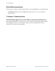
Chapter 1 Introduction This chapter contains a description of the GPIB-120A, lists what you need to get started and optional equipment you can order, and explains how to unpack the GPIB-120A. Description of the GPIB-120A The GPIB-120A is a high-speed bus expander/isolator with the following features: • It is transparent to user software. • It electrically isolates two GPIB systems. • It expands the GPIB to interface up to 28 devices.
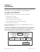
Introduction Chapter 1 GPIB Computer Printer Multimeter Signal Generator (Controller, Talker, and Listener) (Listener) (Talker and Listener) (Listener) Unit Under Test Figure 1-2. Typical GPIB-120A Extension System (Logical Configuration) With the GPIB-120A, it is possible to overcome the following two configuration restrictions imposed by the ANSI/IEEE Standard 488.1-1987: • An electrical loading limit of 15 devices per contiguous bus.
Chapter 1 Introduction What You Need to Get Started One of the following GPIB-120A Bus Expanders/Isolators: GPIB-120A (100 to 120 VAC) GPIB-120A (220 to 240 VAC) 2.2 m, 125 VAC Power Cord (When connected to a power source, this cord connects the equipment chassis to power ground.) Optional Equipment You can contact National Instruments to order any of the following optional equipment.
Chapter 2 Connection This chapter contains information for connecting your GPIB-120A. Danger: The GPIB-120A does not generate high voltages; however, you must use extreme caution if your system or application can cause high voltages on the shield or logic ground of the GPIB cable you attach to the electrically isolated connector (GPIB Port B) located on the rear panel of the GPIB-120A. Many GPIB cables use a metal shell to enclose the GPIB piggyback connectors.
Connection Chapter 2 Placing Your Instruments Identify the instruments or devices in your system that are sensitive to ground loop noise. In the next section, Connecting the GPIB-120A, you will connect these instruments or devices to Bus B of your GPIB-120A. Then, you will connect the other instruments or devices to Bus A. Usually you connect your computer or other device acting as the GPIB System Controller to Bus A. Connecting the GPIB-120A To connect the GPIB-120A, follow these instructions: 1.
Chapter 3 Theory of Operation This chapter describes the operational theory of the GPIB-120A. This chapter assumes that you have a basic knowledge of the GPIB. If you are a first-time user or you would like to review the basics, refer to Appendix A, Operation of the GPIB, for a history and the basic operation of the GPIB.
Theory of Operation Chapter 3 The circuitry on each side of the expansion monitors local GPIB states and converts the signals monitored into X signals (for transmit) which drive the R signals (for receive) on the opposite side of the expansion. The X signals are optically isolated from the R signals. Each GPIB signal is sensed or driven depending on the System Controller, Active Controller, and Source Handshake states of each side of the expansion.
Chapter 3 Theory of Operation If a GPIB device on Bus A asserts DAV, the Bus A Source Handshake state becomes true and the Bus B Source Handshake state becomes false. If a GPIB device on Bus B asserts DAV, the Bus B Source Handshake state becomes true and the Bus A Source Handshake state becomes false. Bus A and Bus B Source Handshake states also become false when a parallel poll begins or when the ATN signal changes states.
Theory of Operation Chapter 3 Acceptable Identification Codes Bus A and Bus B of the GPIB-120A are each capable of appearing as a GPIB device having the GPIB capabilities listed in Table 3-1. For a complete description of each code, consult the ANSI/IEEE Standard 488.1-1987, IEEE Standard Digital Interface for Programmable Instrumentation. Table 3-1.
Appendix A Operation of the GPIB This appendix contains a brief history of the GPIB and describes the operation of the GPIB. History of the GPIB The original GPIB was designed by Hewlett-Packard (where it is called the HP-IB) to connect and control programmable instruments manufactured by Hewlett-Packard. Because of its high data transfer rates of up to 1 Mbytes/s, the GPIB quickly gained popularity in other applications such as intercomputer communication and peripheral control.
Operation of the GPIB Appendix A Talkers, Listeners, and Controller There are three types of GPIB communicators: Talkers, Listeners, and Controllers. A Talker sends data messages to one or more Listeners. The Controller manages the flow of information on the GPIB by sending commands to all devices. Devices can be Listeners, Talkers, and/or Controllers. A digital voltmeter, for example, is a Talker and may be a Listener as well.
Appendix A Operation of the GPIB GPIB Signals and Lines The interface system consists of 16 signal lines and 8 ground return or shield drain lines. The 16 signal lines are divided into the following three groups. • Eight data lines • Three handshake lines • Five interface management lines Data Lines The eight data lines, DI01 through DI08, carry both data and command messages.
Operation of the GPIB Appendix A Interface Management Lines Five lines are used to manage the flow of information across the interface. ATN (Attention) The Controller drives ATN true when it uses the data lines to send commands and false when it allows a Talker to send data messages. IFC (Interface Clear) The System Controller drives the IFC line to initialize the bus and become CIC.
Appendix A Operation of the GPIB Physical and Electrical Characteristics Devices are usually connected with a cable assembly consisting of a shielded 24 conductor cable with both a plug and receptacle connector at each end. With this design, devices can be linked in either a linear configuration (shown in Figure A-2) or a star configuration (shown in Figure A-3), or a combination of the two. The standard connector is the Amphenol or Cinch Series 57 Microribbon or Amp Champ type.
Operation of the GPIB Appendix A Figure A-2.
Appendix A Operation of the GPIB Figure A-3.
Operation of the GPIB Appendix A Configuration Restrictions: The Role of Expanders and Extenders To achieve the high data transfer rate for which the GPIB is designed, the physical distance between devices and the number of devices on the bus are limited. The following restrictions are typical: • A maximum separation of 4 m between any two devices and an average separation of 2 m over the entire bus. • A maximum total cable length of 20 m.
Appendix B Specifications This appendix lists the specifications of the GPIB-120A. Table B-1. System Configuration Configuration Specification Loading per expansion Up to 14 additional devices GPIB driver output circuit and T1 timing of source device No restrictions Note: T1 is the data settling time (DIO valid to DAV) and varies according to the type of drivers and the system configuration used. Table B-2.
Specifications Appendix B Table B-3. Electrical Characteristics Characteristic Specification Isolation 60 V operating 1600 V breakdown Power supply selectable 90 to 130 VAC, 235 mA, (250 mA, 250 V, slow blow), 50 to 60 Hz or 180 to 260 VAC, 120 mA, (200 mA, 250 V, slow blow), 50 to 60 Hz GPIB interface load One standard load, AC and DC Power 27 VA typical Table B-4.
Appendix C Multiline Interface Messages This appendix contains an interface message reference list, which describes the mnemonics and messages that correspond to the interface functions. These multiline interface messages are sent and received with ATN TRUE. For more information on these messages, refer to the ANSI/IEEE Standard 488.1-1987, IEEE Standard Digital Interface for Programmable Instrumentation.
Multiline Interface Messages Appendix C Multiline Interface Messages Hex Oct Dec ASCII 00 01 02 03 04 05 06 07 000 001 002 003 004 005 006 007 0 1 2 3 4 5 6 7 08 09 0A 0B 0C 0D 0E 0F 010 011 012 013 014 015 016 017 8 9 10 11 12 13 14 15 BS HT LF VT FF CR SO SI 10 11 12 13 14 15 16 17 020 021 022 023 024 025 026 027 16 17 18 19 20 21 22 23 DLE DC1 DC2 DC3 DC4 NAK SYN ETB 18 19 1A 1B 1C 1D 1E 1F 030 031 032 033 034 035 036 037 24 25 26 27 28 29 30 31 CAN EM SUB ESC FS GS RS US NUL SOH STX
Appendix C Multiline Interface Messages Multiline Interface Messages Hex Oct 40 41 42 43 44 45 46 47 100 101 102 103 104 105 106 107 64 65 66 67 68 69 70 71 @ A B C D E F G 48 49 4A 4B 4C 4D 4E 4F 110 111 112 113 114 115 116 117 72 73 74 75 76 77 78 79 50 51 52 53 54 55 56 57 120 121 122 123 124 125 126 127 58 59 5A 5B 5C 5D 5E 5F 130 131 132 133 134 135 136 137 PPE PPU SDC SPD Dec ASCII Msg Hex Oct Dec MTA0 MTA1 MTA2 MTA3 MTA4 MTA5 MTA6 MTA7 60 61 62 63 64 65 66 67 140 141 142 143 14
Appendix D Customer Communication For your convenience, this appendix contains forms to help you gather the information necessary to help us solve technical problems you might have as well as a form you can use to comment on the product documentation. Filling out a copy of the Technical Support Form before contacting National Instruments helps us help you better and faster. National Instruments provides comprehensive technical assistance around the world. In the U.S.
Technical Support Form ___________________________________________________ Photocopy this form and update it each time you make changes to your software or hardware, and use the completed copy of this form as a reference for your current configuration. Completing this form accurately before contacting National Instruments for technical support helps our applications engineers answer your questions more efficiently.
GPIB-120A Hardware and Software Configuration Form Record the settings and revisions of your hardware and software on the line located to the right of each item. Complete this form each time you revise your software or hardware configuration, and use this form as a reference for your current configuration. Completing this form accurately before contacting National Instruments for technical support helps our applications engineers answer your questions efficiently.
Documentation Comment Form National Instruments encourages you to comment on the documentation supplied with our products. This information helps us provide quality products to meet your needs. Title: GPIB-120A User Manual Edition Date: October 1994 Part Number: 370893A-01 Please comment on the completeness, clarity, and organization of the manual. If you find errors in the manual, please record the page numbers and describe the errors. Thank you for your help.
Glossary ___________________________________________________ Prefix ° % A AC ANSI ASCII ATN C CIC CPU DAV DC DIO EMI EOI FCC GPIB Hz IFC in.