
User Guide

Contents
FieldPoint FP-3000 User Manual xii
©
National Instruments Corporation
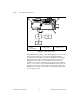
Figure 2-12. FP-3000 Connector Pinout.................................................................... 2-12
Figure 2-13. LEDs on the FP-3000............................................................................ 2-12
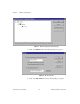
Figure 2-14. FP-3000 Firmware Update Dialog Box ................................................ 2-16
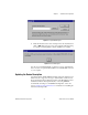
Figure 2-15. FP-3000 Search Dialog Box ................................................................. 2-17
Figure 2-16. Select FP-3000 Module Dialog Box..................................................... 2-18
Figure 3-1. Setting the Channel Dialog Box ........................................................... 3-3
Figure 3-2. Downloading Configuration Dialog Box.............................................. 3-5
Figure 3-3. Set the Input Range and Thermocouple Type Dialog Box................... 3-8
Figure 3-4. PID Block Connections Dialog Box..................................................... 3-14
Figure 3-5. High Limit Alarm Parameters Dialog Box ........................................... 3-16
Figure 3-6. PID Alarm Connection Dialog Box...................................................... 3-17
Figure 4-1. PID Function Block Application Dialog Box....................................... 4-6
Figure A-1. Configuration Toggle Switches ............................................................ A-1
Figure D-1. Parameter Connections for Cascade Initialization................................ D-2
Figure D-2. Remote Cascade Model ........................................................................ D-3
Tables
Table 2-1. Description of Fieldbus NETWORK LED States ............................... 2-13
Table 2-2. STATUS LED Flashes and Corresponding Error Conditions ............. 2-14
Table 4-1. CDO Block Interlock Priorities ........................................................... 4-3
Table 4-2. Function Blocks and FieldPoint Modules............................................. 4-5
Table 4-3. Quality Values ..................................................................................... 4-9
Table 4-4. Limit Values ......................................................................................... 4-10
Table 4-5. Target Modes ....................................................................................... 4-10
Table 4-6. Actual Modes ....................................................................................... 4-11
Table 4-7. Configuration Options .......................................................................... 4-13
Table 4-8. Device Options ..................................................................................... 4-13
Table 4-9. Execution Statistics .............................................................................. 4-14
Table 4-10. Module Status ...................................................................................... 4-15
Table 4-11. Block Events ........................................................................................ 4-17
Table B-1. Fieldbus Communication Problems ..................................................... B-2
Table B-2. I/O Module Problems ........................................................................... B-3
Table B-3. Generic Software Configuration Problems .......................................... B-4
Table B-4. Resource Block Configuration Problems ............................................. B-6
Table C-1. Error Codes .......................................................................................... C-3
Table C-2. Block Reset Options ............................................................................ C-4