Fieldbus FBUS-HSE/H1 Linking Device (LD) User Manual FBUS-HSE/H1 LD User Manual May 2003 Edition Part Number 370728A-01
Support Worldwide Technical Support and Product Information ni.
Important Information Warranty The FBUS-HSE/H1 Linking Device (LD) is warranted against defects in materials and workmanship for a period of one year from the date of shipment, as evidenced by receipts or other documentation. National Instruments will, at its option, repair or replace equipment that proves to be defective during the warranty period. This warranty includes parts and labor.
Compliance FCC/Canada Radio Frequency Interference Compliance Determining FCC Class The Federal Communications Commission (FCC) has rules to protect wireless communications from interference. The FCC places digital electronics into two classes. These classes are known as Class A (for use in industrial-commercial locations only) or Class B (for use in residential or commercial locations). All National Instruments (NI) products are FCC Class A products.
Contents About This Manual How To Use the Manual Set..........................................................................................vii Conventions ...................................................................................................................vii Related Documentation..................................................................................................viii Chapter 1 Overview of FBUS-HSE/H1 Linking Device (LD) Hardware Product Overview ..............................
Contents Appendix D Technical Support and Professional Services Glossary Index FBUS-HSE/H1 LD User Manual vi ni.
About This Manual This manual describes the mechanical and electrical aspects of the FBUS-HSE/H1 Linking Device (LD) and contains information concerning its installation and operation. The FBUS-HSE/H1 LD product is a High Speed Ethernet to Foundation H1 Linking Device. How To Use the Manual Set Begin by reading the Getting Started with Your FBUS-HSE/H1 Linking Device manual, a brief quick-start manual that describes how to set up and get started with your kit using the default settings.
About This Manual programs, subprograms, subroutines, device names, functions, operations, variables, filenames and extensions, and code excerpts. Related Documentation The following documents contain information you might find helpful as you read this manual: FBUS-HSE/H1 LD User Manual • Foundation Fieldbus Specification: System Architecture • NI-FBUS Configurator User Manual • Getting Started with Your HSE Linking Device and the NI-FBUS Software viii ni.
Overview of FBUS-HSE/H1 Linking Device (LD) Hardware 1 This chapter provides an overview of the FBUS-HSE/H1 Linking Device (LD) hardware. Product Overview High Speed Ethernet (HSE) is an extension to the Foundation Fieldbus specification and is governed by the Foundation Fieldbus organization. HSE compliments the Foundation Fieldbus H1 network (31.25 kb/s) specification by offering a high speed (10 Mb/s) link to H1 segments.
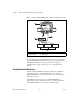
Chapter 1 Overview of FBUS-HSE/H1 Linking Device (LD) Hardware Figure 1-1 shows an FBUS-HSE/H1 LD connected to an Ethernet network. 1 5 2 4 3 1 2 FBUS-HSE/H1 LD Ethernet Cable 3 4 Ethernet Devices Ethernet Hub 5 H1 Network Ports Figure 1-1. Typical Ethernet Network Setup In a distributed application, many Fieldbus H1 segments are networked together using HSE LDs. With Ethernet, you can use an unlimited number of Fieldbus H1 segments.
Chapter 1 Overview of FBUS-HSE/H1 Linking Device (LD) Hardware Once configured, the linking device permits HMI software on any PC connected to an FBUS-HSE/H1 LD to access and monitor Fieldbus devices as if the HMI were directly connected to the Fieldbus network. System Requirements This section describes the hardware and software components you need before you can use the linking device. You also should review the README.TXT file on the linking device setup disk for the latest information.
2 Hardware Installation and Configuration Installing the FBUS-HSE/H1 LD The FBUS-HSE/H1 LD has a simple rail clip for reliable mounting onto a standard 35 mm DIN rail. Complete the following steps to mount the FBUS-HSE/H1 LD on a DIN rail. 1. Use a flathead screwdriver to open the DIN rail clip to the unlocked position, as shown in Figure 2-1. Rail Clip Locked Rail Clip Unlocked Figure 2-1. DIN Rail Clip 2.
Chapter 2 Hardware Installation and Configuration 2 3 1 4 1 2 Cover Lip 3 4 35 mm DIN Rail Press on to Rail Figure 2-2. Mounting the FBUS-HSE/H1 LD on a DIN Rail 3. Slide the FBUS-HSE/H1 LD to the desired position along the DIN rail. After the FBUS-HSE/H1 LD is in position, lock it to the DIN rail by pushing the rail clip to the locked position, as shown in Figure 2-1.
Chapter 2 Hardware Installation and Configuration Mounting the FBUS-HSE/H1 LD to a Panel Complete the following steps to install the optional Fieldbus network panel mount accessory and mount the FBUS-HSE/H1 LD network module to a panel. You can order the panel mount accessory from National Instruments. 1. Use a flathead screwdriver to open the rail clip to the unlocked position, as shown in Figure 2-1. 2. Snap the panel mount accessory onto the module, as shown in Figure 2-3. Figure 2-3.
Chapter 2 Hardware Installation and Configuration Connect Your FBUS-HSE/H1 LD to the Network Connect the RJ-45 Ethernet port of the FBUS-HSE/H1 LD to an Ethernet hub using a standard Category 5 Ethernet cable. You also can connect an FBUS-HSE/H1 LD directly to a computer using an Ethernet crossover cable. Note Do not use a cable longer than 100 m. If you are using a 10 Mbps Ethernet, National Instruments recommends using a Category 5 shielded twisted-pair Ethernet cable.
Chapter 2 Hardware Installation and Configuration Cabling If you build your own cables, the following table shows the standard Ethernet cable wiring connections for both normal and crossover cables. Table 2-1.
Chapter 2 Hardware Installation and Configuration Connect the FBUS-HSE/H1 LD to the Fieldbus Network The FBUS-HSE/H1 LD can be one of up to 32 devices connected to a Fieldbus H1 network. The connection is made through one of the two 9-pin male D-sub Fieldbus H1 connectors on the FBUS-HSE/H1 LD, shown in Figure 2-4. Use a Fieldbus cable with a 9-pin female D-sub connector to connect the FBUS-HSE/H1 LD to a properly terminated Fieldbus network.
Chapter 2 Hardware Installation and Configuration Connect Power to the FBUS-HSE/H1 LD Each FBUS-HSE/H1 LD on your network requires an 11-30 VDC power supply. The power connector is a 6-pin screw terminal power connector whose pinout is shown in Figure 2-7. v 11-30 VDC Backup Power Supply (Optional) + – c c c v v V To Adjacent Device (Optional Connection) C 11-30 VDC Primary Power Supply + – Figure 2-7.
Resetting the FBUS-HSE/H1 LD A If the FBUS-HSE/H1 LD cannot communicate with the network, you can configure the Ethernet settings through NI-FBUS software. When you configure the device, it attempts to confirm that the new settings are valid. However, if the configuration process is interrupted or the FBUS-HSE/H1 LD is moved to a new network with different settings, the device might not be able to communicate with the network. If this occurs, you can manually reset the unit to its factory settings.
Appendix A Resetting the FBUS-HSE/H1 LD Reset Switch Made in the USA Normal Reset Figure A-1. FBUS-HSE/H1 LD Reset Switch 3. Looking at the FBUS-HSE/H1 LD so that the label is upright, as shown in Figure A-1, use a pen or a small screwdriver to move the Reset switch to the right. 4. Power up the FBUS-HSE/H1 LD and wait for the red STATUS LED to flash. When the LED flashes, the FBUS-HSE/H1 LD is in Reset mode. 5. Power down the FBUS-HSE/H1 LD and move the Reset switch back to the left. 6.
B Troubleshooting LED Indicators Hardware The FBUS-HSE/H1 LD has seven LED indicators on the top panel and three LEDs on the front panel, as shown in Figure B-1.
Appendix B Troubleshooting 1 1 2 3 H1 Port1 Network Status Power Process 2 4 3 4 5 6 5 7 6 Ethernet Status Module Status TX 7 8 9 8 9 RX H1 Port 2 Network Status Link Figure B-1. LEDs on the FBUS-HSE/H1 LD Ethernet LEDs The six Ethernet LEDs are located on the top panel. The green POWER LED is lit while the FBUS-HSE/H1 LD is powered up. This LED indicates that the power supply connected to the FBUS-HSE/H1 LD is acceptable. FBUS-HSE/H1 LD User Manual B-2 ni.
Appendix B Caution Troubleshooting Do not power down the FBUS-HSE/H1 LD while the PROCESS LED is lit. The green PROCESS LED is lit when you update the nonvolatile flash memory of the FBUS-HSE/H1 LD. If you want to change network settings, save channel settings or power-up values, or upgrade its firmware, you need to update the nonvolatile flash memory. The red Ethernet STATUS LED is lit when the FBUS-HSE/H1 LD detects an error.
Appendix B Troubleshooting Table B-1. Ethernet STATUS LED Flashes and Corresponding Error Conditions Number of Flashes Error Condition 0 (stays lit) The FBUS-HSE/H1 LD has not been configured with a proper IP address. 1 The FBUS-HSE/H1 LD is in Reset mode. Switch the FBUS-HSE/H1 LD back to Normal mode by powering down the device and sliding the switch underneath the module. 2 The FBUS-HSE/H1 LD has detected an error in its firmware.
Appendix B Troubleshooting Table B-2. Interpretation of FBUS-HSE/H1 LD Module STATUS LED (Continued) LED State Meaning Flashing red Major recoverable fault Solid red Major unrecoverable fault Standby state indicates the linking device has passed all self tests and is ready to operate. However, it is not functioning because no active Ethernet segment is configured. Operational state indicates the linking device has left standby state because the necessary network configuration (if any) has occurred.
C Specifications This appendix describes the specifications of the FBUS-HSE/H1 LD. Network Network interface................................... 10BaseT and 100BaseTX Ethernet Device interface ..................................... Foundation Fieldbus H1 Compatibility ......................................... High Speed Ethernet Communication rates ............................. 10 Mbps, autonegotiated for HSE, 31.25 Kbps for H1 Cabling distance.....................................
Appendix C Specifications Safety This product is designed to meet the requirements of the following standards for safety and electrical equipment for measurement, control, and laboratory use: Note • IEC 60950, EN 60950 • UL 1950, UL 60950 • CAN/CSA C22.2 No. 60950 For UL and other safety certifications, refer to the product label or to ni.com. Electromagnetic Compatibility Emissions................................................EN 55011 Class A at 10 m FCC Part 15A above 1 GHz Immunity .........
Technical Support and Professional Services D Visit the following sections of the National Instruments Web site at ni.com for technical support and professional services: • Support—Online technical support resources include the following: – Self-Help Resources—For immediate answers and solutions, visit our extensive library of technical support resources available in English, Japanese, and Spanish at ni.com/support.
Appendix D Technical Support and Professional Services • Calibration Certificate—If your product supports calibration, you can obtain the calibration certificate for your product at ni.com/calibration. If you searched ni.com and could not find the answers you need, contact your local office or NI corporate headquarters. Phone numbers for our worldwide offices are listed at the front of this manual. You also can visit the Worldwide Offices section of ni.
Glossary Symbol Prefix Value m milli 10 –3 k kilo 10 3 M mega 10 6 A A Amperes. A/D Analog-to-digital converter Alarm. A notification the NI-FBUS Communications Manager software sends when it detects that a block leaves or returns to a particular state. address character Code that identifies a specific location (or series of locations) in memory. administrative function NI-FBUS function that deals with administrative tasks, such as returning descriptors and closing descriptors.
Glossary Boolean Logical relational system having two values, each the opposite of the other, such as true and false or zero and one. bps Bits per second. buffer Temporary storage for acquired or generated data. bus The group of conductors that interconnect individual circuitry in a computer. Typically, a bus is the expansion vehicle to which I/O or other devices are connected. Examples of PC busses are the ISA and PCI buses. C C Celsius. cable A number of wires and shield in a single sheath.
Glossary device tag A name you assign to a Fieldbus device. DI Discrete input. digital Pertaining to data (signals) in the form of discrete (separate/pulse form) integral values. directory A structure for organizing files into convenient groups. A directory is like an address showing where files are located. A directory can contain files or subdirectories of files. distributed control Process control distributed among several devices connected by a network. DO Discrete output.
Glossary Fieldbus network address Location of a board or device on the Fieldbus; theFieldbus node address. Foundation Fieldbus specification Communications network specification created by the Fieldbus Foundation. G ground An intentional or accidental conducting path between an electrical system or circuit and the earth or some conducting body acting in place of the earth. A ground is often used as the common wiring point or reference in a circuit. H H1 31.25 kbit/second type of Fieldbus.
Glossary L LAS See Link Active Scheduler. LD Linking device. LED Light-emitting diode. link A Foundation Fieldbus network is made up of devices connected by a serial bus. This serial bus is called a link. Also known as a segment. Link Active Scheduler Fieldbus device currently controlling access to the Fieldbus. A device that is responsible for keeping a link operational. The LAS executes the link schedule, circulates tokens, distributes time, and probes for new devices.
Glossary node Junction or branch point in a circuit. non-volatile memory Memory that does not require electricity to hold data. O object An element of an object dictionary. P parameter One of a set of network-visible values that makes up a function block. PC Personal computer. polarity Term used to describe positive and negative charges. poll To repeatedly inspect a variable or function block to acquire data. port A communications connection on a computer or remote controller.
Glossary sensor A device that responds to a physical stimulus (heat, light, sound, pressure, motion, flow, and so on), and produces a corresponding electrical signal. server Device that receives a message request. service A service allows user applications to send messages to each other across Fieldbus using a standard set of message formats. T tag A name you can define for a block, virtual field device, or device. terminator A device used to absorb the signal at the end of a wire.
Glossary W Waveform FBUS-HSE/H1 LD User Manual Multiple voltage readings taken at a specific sampling rate. G-8 ni.
Index C Ethernet cable pinouts (figure), 2-5 cable wiring connections (table), 2-5 connecting to the network, 2-3 typical network setup (figure), 1-2 Ethernet LEDs LINK, B-2 POWER, B-2 PROCESS, B-2 RX, B-2 STATUS, B-2 TX, B-2 Ethernet STATUS LED flashes and corresponding errors (table), B-4 example code, D-1 cables, 2-5 calibration certificate, D-2 CE compliance, C-2 compatibility information, 1-3 configuration and monitoring, 1-2 connecting to the Fieldbus network, 2-6 connector pinout (figure), 2-6 cont
Index Ethernet LEDs figure, B-2 LINK, B-2 POWER, B-2 PROCESS, B-2 RX, B-2 STATUS, B-2 TX, B-2 installation and configuration, 2-1 installing the network panel accessory (figure), 2-3 LEDs Ethernet STATUS flashes and corresponding errors (table), B-4 H1 network status LEDs (table), B-5 troubleshooting, B-1 module STATUS LED (table), B-4 mounting on a DIN rail (figure), 2-2 mounting to a panel, 2-3 overview, 1-1 power connection, 2-7 pinout (figure), 2-7 power on, 2-7 system requirements, 1-3 LEDs Ethernet
Index L R LEDs Ethernet LEDs, B-2 figure, B-2 H1 network status LEDs (table), B-5 module STATUS LED (table), B-4 on top panel (figure), B-1 POWER, 2-7 troubleshooting, B-1 related documentation, viii reset switch (figure), A-2 resetting, A-1 S software HMI, 1-3 NI-FBUS, using to configure Ethernet settings, A-1 system requirements, 1-3 software drivers, D-1 specifications CE compliance, C-2 electromagnetic compatibility, C-2 environmental, C-1 mechanical dimensions, C-1 network, C-1 operating, C-1 safe
Index W Web professional services, D-1 technical support, D-1 worldwide technical support, D-2 FBUS-HSE/H1 LD User Manual I-4 ni.