FieldPoint™ Operating Instructions FP-AI-110 and cFP-AI-110 Eight-Channel, 16-Bit Analog Input Modules These operating instructions describe how to install and use the FP-AI-110 and cFP-AI-110 analog input modules (referred to inclusively as the [c]FP-AI-110). For information about configuring and accessing the [c]FP-AI-110 over a network, refer to the user manual for the FieldPoint network module you are using.
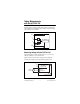
To install the FP-AI-110, refer to Figure 1 and complete the following steps: 1. Slide the terminal base key to either position X (used for any module) or position 1 (used for the FP-AI-110). 2. Align the FP-AI-110 alignment slots with the guide rails on the terminal base. 3. Press firmly to seat the FP-AI-110 on the terminal base. When the FP-AI-110 is firmly seated, the latch on the terminal base locks it into place.
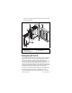
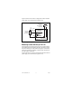
(10 lb ⋅ in.) of torque. The nylon coating on the screws prevents them from loosening. 4 3 5 2 4 2 1 1 2 3 cFP-DI-300 Captive Screws cFP Controller Module 4 5 Screw Holes cFP Backplane Figure 2. Installing the cFP-AI-110 Wiring the [c]FP-AI-110 The FP-TB-x terminal base has connections for each of the eight input channels and for an external power supply to power field devices. The cFP-CB-x connector block provides the same connections.
is 2 A or less and the maximum current through any VSUP terminal is 1 A or less. Install a 2 A maximum, fast-acting fuse between the external power supply and the V terminal on each channel. The wiring diagrams in this document show fuses where appropriate. Table 1 lists the terminal assignments for the signals associated with each channel. The terminal assignments are the same for the FP-TB-x terminal bases and the cFP-CB-x connector blocks. Table 1.
Taking Measurements with the [c]FP-AI-110 The [c]FP-AI-110 has eight single-ended input channels. All eight channels share a common ground reference that is isolated from other modules in the FieldPoint system. Figure 3 shows the analog input circuitry on one channel. V VSUP VIN IIN Filter 16-Bit Isolated ADC Filter COM C Figure 3.
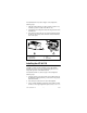
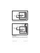
Figure 5 shows how to connect a voltage source with an external power supply to one channel of the [c]FP-AI-110. 1A Max Powered + Voltage OUT Transducer – 10–30 VDC + External Power Supply – (Optional) 2A Max C V VSUP To Analog Input Circuitry VIN IIN COM To Next Channel [c]FP-AI-110 Figure 5. Voltage Source with External Power Supply Measuring Current with the [c]FP-AI-110 The input ranges for current sources are 0–20, 4–20, and ±20 mA.
C V VSUP VIN 1A Max Current Source To Analog Input Circuitry IIN COM To Next Channel [c]FP-AI-110 Figure 6. Current Source without External Power Supply Figure 7 shows how to connect a current source with an external power supply to one channel of the [c]FP-AI-110. 1A Max Loop-Powered Current Transducer 10–30 VDC + External Power Supply – (Optional) 2A Max C V VSUP VIN To Analog Input Circuitry IIN COM To Next Channel [c]FP-AI-110 Figure 7.
Overranging The [c]FP-AI-110 has an overranging feature that measures a little beyond the nominal values of each range. For example, the actual measurement limit of the ±10 V range is ±10.4 V. The overranging feature enables the [c]FP-AI-110 to compensate for field devices with span errors of up to +4% of full scale. Also, with the overranging feature, a noisy signal near full scale does not create rectification errors. Filter Settings Three filter settings are available for each channel.
sampling rate is faster than the rate at which the network module polls the [c]FP-AI-110 for data. Status Indicators The [c]FP-AI-110 has two green status LEDs, POWER and READY. After you insert the [c]FP-AI-110 into a terminal base or backplane and apply power to the connected network module, the green POWER LED lights and the [c]FP-AI-110 informs the network module of its presence. When the network module recognizes the [c]FP-AI-110, it sends initial configuration information to the [c]FP-AI-110.
working voltages of 250 Vrms1. Safety standards (such as those published by UL and IEC) require the use of double insulation between hazardous voltages and any human-accessible parts or circuits. Never try to use any isolation product between human-accessible parts (such as DIN rails or monitoring stations) and circuits that can be at hazardous potentials under normal conditions, unless the product is specifically designed for such an application, as is the [c]FP-AI-110.
• Operate the [c]FP-AI-110 only at or below Pollution Degree 2. Pollution Degree 2 means that only nonconductive pollution occurs in most cases. Occasionally, however, a temporary conductivity caused by condensation must be expected. • Operate the [c]FP-AI-110 at or below Measurement Category II. Measurement Category II is for measurements performed on circuits directly connected to the low-voltage installation.
Safety Guidelines for Hazardous Voltages If hazardous voltages are connected to the module, take the following precautions. A hazardous voltage is a voltage greater than 42.4 Vpeak or 60 VDC to earth ground. Ensure that hazardous voltage wiring is performed only by qualified personnel adhering to local electrical standards. Caution Caution Do not mix hazardous voltage circuits and human-accessible circuits on the same module.
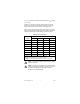
Effective resolution by input signal range and filter setting Nominal Input Range With Overranging Effective Resolution with 50 or 60 Hz Filter Enabled* Effective Resolution with 500 Hz or No Filter Enabled* Voltage ±60 mV ±300 mV ±1 V ±5 V ±10 V 0–1 V 0–5 V 0–10 V ±65 mV ±325 mV ±1.04 V ±5.2 V ±10.4 V 0–1.04 V 0–5.2 V 0–10.4 V 3 µV 16 µV 40 µV 190 µV 380 µV 20 µV 95 µV 190 µV 25 µV 100 µV 300 µV 1,500 µV 3,000 µV 300 µV 1,500 µV 3,000 µV Current 0–20 mA 4–20 mA ±20 mA 0–21 mA 3.
Input current 25 °C........................................... 400 pA typ, 1 nA max 70 °C........................................... 3 nA typ, 15 nA max Input noise (with 50 or 60 Hz filter enabled) ±60 mV range............................. ±3 LSB1 peak-to-peak ±300 mV range........................... ±2 LSB peak-to-peak Other ranges ...............................
Nominal Input Range Typical Accuracy at –40 to 70 °C (% of Reading; % of Full Scale) Warranted Accuracy at –40 to 70 °C (% of Reading; % of Full Scale) 0–1 V ±0.06%; ±0.025% ±0.10%; ±0.12% 0–5 V ±0.07%; ±0.007% ±0.11%; ±0.03% 0–10 V ±0.07%; ±0.005% ±0.11%; ±0.02% Note Full scale is the maximum value of the nominal input range. For example, for the ±10 V input range, full scale is 10 V and ±0.01% of full scale is 1 mV. Gain error drift..................................
Physical Characteristics Indicators .......................................... Green POWER and READY indicators Weight FP-AI-110................................... 140 g (4.8 oz) cFP-AI-110................................. 110 g (3.7 oz) Power Requirements Power from network module ............ 350 mW Safety Isolation Voltage Channel-to-ground isolation Continuous ................................. 250 Vrms, Measurement Category II Dielectric withstand....................
Operating shock (IEC 60068-2-27).............................. 50 g, 3 ms half sine, 18 shocks at 6 orientations; 30 g, 11 ms half sine, 18 shocks at 6 orientations Safety This product is designed to meet the requirements of the following standards of safety for electrical equipment for measurement, control, and laboratory use: • IEC 61010-1, EN 61010-1 • UL 61010-1 • CAN/CSA-C22.2 No. 61010-1 For UL, hazardous location, and other safety certifications, refer to the product label or visit ni.
CE Compliance This product meets the essential requirements of applicable European Directives, as amended for CE marking, as follows: Low-Voltage Directive (safety)......... 73/23/EEC Electromagnetic Compatibility Directive (EMC) ............................... 89/336/EEC Note Refer to the Declaration of Conformity (DoC) for this product for any additional regulatory compliance information. To obtain the DoC for this product, visit ni.
Where to Go for Support For more information about setting up the FieldPoint system, refer to these National Instruments documents: • FieldPoint network module user manual • Other FieldPoint I/O module operating instructions • FieldPoint terminal base and connector block operating instructions Go to ni.com/support for the most current manuals, examples, and troubleshooting information. National Instruments corporate headquarters is located at 11500 North Mopac Expressway, Austin, Texas, 78759-3504.
National Instruments, NI, ni.com, and LabVIEW are trademarks of National Instruments Corporation. Refer to the Terms of Use section on ni.com/legal for more information about National Instruments trademarks. Other product and company names mentioned herein are trademarks or trade names of their respective companies. For patents covering National Instruments products, refer to the appropriate location: Help»Patents in your software, the patents.txt file on your CD, or ni.com/patents.