DIO 6533 User Manual High-Speed Digital I/O Boards for PCI, PXI, CompactPCI, AT, EISA, or PCMCIA Bus Systems July 1997 Edition Part Number 321464B-01 © Copyright 1997 National Instruments Corporation. All rights reserved.
Internet Support support@natinst.com E-mail: info@natinst.com FTP Site: ftp.natinst.com Web Address: http://www.natinst.com Bulletin Board Support BBS United States: (512) 794-5422 BBS United Kingdom: 01635 551422 BBS France: 01 48 65 15 59 Fax-on-Demand Support (512) 418-1111 Telephone Support (U.S.
Important Information Warranty The PCI-DIO-32HS, PXI-6533, AT-DIO-32HS, and DAQCard-6533 devices are warranted against defects in materials and workmanship for a period of one year from the date of shipment, as evidenced by receipts or other documentation. National Instruments will, at its option, repair or replace equipment that proves to be defective during the warranty period. This warranty includes parts and labor.
Table of Contents About This Manual Organization of This Manual ........................................................................................ xi Conventions Used in This Manual................................................................................ xii National Instruments Documentation ........................................................................... xii Related Documentation.................................................................................................
Table of Contents AT Device Configuration ............................................................................................. 2-5 Bus Interface .................................................................................................. 2-5 Plug and Play Mode......................................................................... 2-5 Switchless Data Acquisition ............................................................ 2-5 Base I/O Address Selection.......................................
Table of Contents Timing Connections...................................................................................................... 4-13 Pull-Up and Pull-Down Connections ........................................................................... 4-13 Power Connections ....................................................................................................... 4-14 Field Wiring and Termination ......................................................................................
Table of Contents Appendix A Specifications Appendix B Optional Adapter Description Appendix C Customer Communication Glossary Index Figures Figure 1-1. The Relationship Between the Programming Environment, NI-DAQ, and Your Hardware ............................................................................... 1-6 Figure 2-1. DAQCard-6533 Completed Installation................................................ 2-4 Figure 3-1. Figure 3-2. Figure 3-3. Figure 3-4. PCI-DIO-32HS/PXI-6533 Block Diagram .....
Table of Contents Figure 5-11. Figure 5-12. Figure 5-13. Figure 5-14. Figure 5-15. Figure 5-16. Figure 5-17. Figure 5-18. Figure 5-19. Figure 5-20. Figure 5-21. Figure 5-22. Figure 5-23. Figure 5-24. Figure 5-25. Figure 5-26. Figure 5-27. Figure 5-28. Figure 5-29. Level-ACK Mode Output Timing ......................................................... 5-13 Leading-Edge Mode Input ..................................................................... 5-15 Leading-Edge Mode Output .............................
About This Manual This manual describes the electrical and mechanical aspects of the DIO 6533 (formerly called DIO-32HS) family of devices, and contains information concerning their operation and programming. Unless otherwise noted, text applies to all devices in the DIO 6533 family. The devices named DIO-32HS and 6533 are the same in functionality; their primary difference is the bus interface.
About This Manual • Appendix B, Optional Adapter Description, describes the optional 68-to-50-pin DIO 6533 device adapter. • Appendix C, Customer Communication, contains forms you can use to request help from National Instruments or to comment on our products. • The Glossary contains an alphabetical list and descriptions of terms used in this manual, including acronyms, abbreviations, definitions, metric prefixes, mnemonics, and symbols.
About This Manual • Getting Started with SCXI—If you are using SCXI, this is the first manual you should read. It gives an overview of the SCXI system and contains the most commonly needed information for the modules, chassis, and software. • Your SCXI hardware user manuals—If you are using SCXI, read these manuals next for detailed information about signal connections and module configuration. They also explain in greater detail how the module works and contain application hints.
About This Manual Customer Communication National Instruments wants to receive your comments on our products and manuals. We are interested in the applications you develop with our products, and we want to help if you have problems with them. To make it easy for you to contact us, this manual contains comment and configuration forms for you to complete. These forms are in Appendix C, Customer Communication, at the end of this manual.
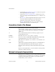
Chapter 1 Introduction This chapter describes the DIO 6533 (DIO-32HS) devices, lists what you need to get started, describes optional equipment, and explains how to unpack your device. About the DIO 6533 Devices Thank you for buying a National Instruments DIO 6533 device. The 6533 devices are 32-bit, parallel digital I/O interfaces for PC-compatible computers, or PXI or CompactPCI chassis. The 6533 devices offer digital data acquisition, digital waveform generation, and high-speed, flexible handshaking.
Chapter 1 Introduction Each 6533 device contains the National Instruments DAQ-DIO chip, providing two independent channels of digital input and output, pattern generation, and handshaking.
Chapter 1 Introduction PXI specific features are implemented on the J2 connector of the CompactPCI bus. Table 1-1 lists the J2 pins used by your PXI-6533 device. Your PXI device is compatible with any CompactPCI chassis with a sub-bus that does not drive these lines. Even if the sub-bus is capable of driving these lines, the PXI device is still compatible as long as those pins on the sub-bus are disabled by default and not ever enabled. Damage may result if these lines are driven by the sub-bus.
Chapter 1 Introduction ❑ One of the following software packages and documentation: NI-DAQ for PC compatibles LabVIEW for Windows LabWindows/CVI ComponentWorks VirtualBench ❑ Appropriate cable: PSHR68-68M (DAQCard-6533 only) Shielded or ribbon cable (for all devices) ❑ Your computer, PXI, or CompactPCI chassis and controller Software Programming Choices There are several options to choose from when programming your National Instruments DAQ hardware.
Chapter 1 Introduction VirtualBench features virtual instruments that combine DAQ products, software, and your computer to create a stand-alone instrument with the added benefit of the processing, display, and storage capabilities of your computer. VirtualBench instruments load and save waveform data to disk in the same forms that can be used in popular spreadsheet programs and word processors.
Chapter 1 Introduction ComponentWorks, LabVIEW, LabWindows/CVI, or VirtualBench Conventional Programming Environment NI-DAQ Driver Software DAQ or SCXI Hardware Personal Computer or Workstation Figure 1-1. The Relationship Between the Programming Environment, NI-DAQ, and Your Hardware You can use your 6533 device, together with other AT (16-bit ISA), PCI, PC, EISA, DAQCard, and DAQPad Series DAQ hardware, with NI-DAQ software for PC compatibles. The PCI-DIO-32HS or AT-DIO-32HS requires version 5.
Chapter 1 Introduction Optional Equipment National Instruments offers a variety of products to use with your 6533 device, including cables, connector blocks, and other accessories, as follows: • Cables and cable assemblies, shielded and ribbon • Connector blocks, shielded and unshielded 50 and 68-pin screw terminals • Real Time System Integration (RTSI) bus cables • SCXI modules and accessories for isolating digital signals, controlling relays, and creating isolated analog outputs • Low channel-c
Chapter 1 Introduction Unpacking Your 6533 device is shipped in an antistatic package to prevent electrostatic damage to the device. Electrostatic discharge can damage several components on the device. To avoid such damage in handling the device, take the following precautions: DIO 6533 User Manual • Ground yourself via a grounding strap or by holding a grounded object. • Touch the antistatic package to a metal part of your computer chassis before removing the device from the package.
Chapter Installation and Configuration 2 This chapter explains how to install and configure your DIO 6533 device. Software Installation Install your software before you install your 6533 device. Refer to the appropriate release notes indicated below for specific instructions on the software installation sequence. If you are using NI-DAQ, refer to your NI-DAQ release notes. Find the installation section for your operating system and follow the instructions given there.
Chapter 2 Installation and Configuration 4. Touch the metal part inside your computer to discharge any static electricity that might be on your clothes or body. 5. Insert the PCI-DIO-32HS into a 5 V PCI slot. It may be a tight fit, but do not force the device into place. 6. Screw the mounting bracket of the PCI-DIO-32HS to the back panel rail of the computer. 7. Visually verify the installation. 8. Replace the top cover of your computer. 9. Plug in and turn on your computer.
Chapter 2 Installation and Configuration 7. Visually verify the installation. 8. Plug in and turn on the PXI or CompactPCI chassis. Installing the AT-DIO-32HS You can install an AT-DIO-32HS in any available AT (16-bit ISA) or EISA expansion slot in your computer. 1. Turn off and unplug your computer. 2. Remove the top cover or access port to the expansion slots. 3. Remove the expansion slot cover on the back panel of the computer. 4.
Chapter 2 Installation and Configuration Portable Computer PCMCIA Socket I/O Cable CB-68 I/O Signals Figure 2-1. DAQCard-6533 Completed Installation Your 6533 device is installed. The device is now ready for software configuration. PCI, PXI, and DAQCard Device Configuration The PCI-DIO-32HS, PXI-6533, and DAQCard-6533 are completely software configurable. The system software automatically allocates all device resources, including base memory address and interrupt level.
Chapter 2 Installation and Configuration AT Device Configuration The plug and play feature of the AT-DIO-32HS makes it completely software configurable. You can use software to configure the base I/O address, DMA channels, and interrupt levels. Bus Interface The AT-DIO-32HS works in either a Plug and Play mode or a switchless mode. These modes dictate how system resources are determined and assigned to the device.
Chapter 2 Installation and Configuration Base I/O Address Selection The AT-DIO-32HS device can be configured to use a base address in the range of 100 to 3E0 hex. The AT-DIO-32HS occupies 16 bytes of address space and must be located on a 16-byte boundary. Therefore, valid addresses include 100, 110, 120, ..., 3D0, 3E0 hex. This selection is software configured and does not require you to manually change any settings on the device.
Chapter 2 Installation and Configuration Table 2-1.
Chapter 2 Installation and Configuration Table 2-1. PC AT I/O Address Map (Continued) I/O Address Range (Hex) Device 3C0 to 3CF Enhanced Graphics Adapter, VGA 3D0 to 3DF Color/Graphics Monitor Adapter, VGA 3E0 to 3EF — 3F0 to 3F7 Diskette Controller 3F8 to 3FF Serial Port 1 (COM1) A79 Reserved for Plug and Play operation Table 2-2 shows the PC AT interrupt assignments. Table 2-2.
Chapter 2 Installation and Configuration Table 2-2. PC AT Interrupt Assignment Map (Continued) IRQ Device 3 Serial Port 2 (COM2) BSC, BSC Alternate Cluster (primary) PC Network, PC Network Alternate WD EtherCard+ – default 3Com EtherLink – default 2 IRQ 8-15 Chain (from interrupt controller 2) 1 Keyboard Controller Output Buffer Full 0 Timer Channel 0 Output Table 2-3 shows the PC AT 16-bit DMA channel assignments. Table 2-3.
Chapter 3 Hardware Overview This chapter provides an overview of the hardware functions of your DIO 6533 device. Each 6533 device contains the National Instruments DAQ-DIO chip, a 32-bit general-purpose digital I/O interface. The DAQ-DIO chip enables the 6533 device to perform single-line and single-point input and output, digital data acquisition, digital waveform generation, and high-speed data transfer using a wide range of handshaking protocols.
Hardware Overview Data Lines (32) Internal FIFOs Data Latches and Drivers DMA/ Interrupt Requests DAQ-DIO Handshaking and Control Counters and Timers Clock Selection Request Processing Bus Interface PCI I/O Channel MITE PCI Interface EEPROM 20 MHz Oscillator Data Lines (32) Control Lines (8) I/O Connector Chapter 3 RTSI Interface RTSI/PXI Trigger Bus Figure 3-1.
Chapter 3 Internal FIFOs Data Latches and Drivers DMA/ Interrupt Requests DAQ-DIO Handshaking and Control Counters and Timers Clock Selection Request Processing Bus Interface AT I/O Channel AT Plug and Play Interface EEPROM 20 MHz Oscillator Data Lines (32) Control Lines (8) I/O Connector Data Lines (16) Hardware Overview RTSI Interface RTSI Bus Figure 3-2.
Hardware Overview Data Lines (16) Internal FIFOs Data Latches and Drivers DMA/ Interrupt Requests DAQ-DIO Handshaking and Control Counters and Timers Clock Selection Request Processing Bus Interface PCMCIA I/O Channel PCMCIA Interface Data Lines (32) Control Lines (8) I/O Connector Chapter 3 20 MHz Oscillator Figure 3-3. DAQCard-6533 Block Diagram Unstrobed I/O The 6533 devices can perform unstrobed I/O, which is basic digital I/O that employs no handshaking or hardware-controlled timing.
Chapter 3 Hardware Overview Strobed I/O—Pattern Generation and Handshaking The 6533 devices can also perform strobed I/O. Strobed I/O is data transfer in which the 6533 hardware regulates timing or performs handshaking functions. The 6533 devices have two handshaking controllers and can perform up to two strobed operations simultaneously. The operations can be input transfers, output transfers, or one of each.
Chapter 3 Hardware Overview A variant of pattern generation is change detection. In change detection, the 6533 device generates an internal request only when the input data changes. This feature allows you to monitor activity on the input lines efficiently, without capturing multiple copies of the same input pattern. See the Pattern and Change Detection section for more information. In full, or two-way, handshaking transfer, control information passes both to and from the peripheral device.
Chapter 3 Hardware Overview Figure 3-4 shows a pattern-detection example. Value to Detect X X X X X X 1 0 Pattern 0 0 0 0 0 0 1 0 Mask 0 0 0 0 0 0 1 1 Polarity Postive: Search for Match Figure 3-4. Pattern Detection Example The 6533 device provides the following two types of pattern detection timing: • Compare all data to the input pattern immediately, without waiting for a request pulse (typically used for start triggers).
Chapter 3 Hardware Overview The pattern mask, which selects the bits that are significant for pattern detection, also applies to change detection. The 6533 device monitors only the significant bits for changes. After detecting a change, however, the 6533 device captures the values of all bits. Change detection can increase CPU and bus efficiency for control applications.
Chapter 3 Hardware Overview expected from the peripheral device. One protocol, burst mode, also uses PCLK signals. The following sections describe the handshaking protocols offered by the 6533 devices. Refer to Table 3-1 for further information on these protocols. For timing details, see Chapter 5, Signal Timing.
Chapter 3 Hardware Overview Burst Mode The 6533 device sends or receives a clock signal to or from the peripheral device over the PCLK line. Every cycle, the 6533 device asserts an ACK signal if ready for a transfer, and the peripheral device, likewise, asserts a REQ signal if ready for a transfer. Each cycle during which both the 6533 device and the peripheral device indicate that they are ready for a transfer, one data point is latched.
Chapter 3 Hardware Overview Table 3-1. 6533 Handshaking Protocols Protocol Peak Rates (MS/s) at Various Cable Lengths 1m REQ and ACK REQ Edge Programmable Polarity That Requests Delay Location Transfer Complementary Protocols 2 or 5 m Asynchronous Protocols 8255 Emulation 5 2.67 Active-low Trailing Between transfers Leading-Edge Pulse Level ACK 3.33 2.5 Programmable Leading Before ACK and between transfers Level ACK LeadingEdge Pulse 3.33 2.
Chapter 3 Hardware Overview Starting a Handshaking Transfer Starting a handshaking transfer correctly protects against incorrect or missed data when the ACK and REQ lines are changing polarity to active-high or active-low. This is particularly important in burst mode because of the potential to miss a lot of data. You can use either of the following two startup methods: • Control the configuration and startup sequence. • Select compatible line polarities and default line levels.
Chapter 3 Hardware Overview Controlling Line Polarities If you cannot control the initialization order of the 6533 device and peripheral device, you can still start a transfer reliably if you select the polarities of the ACK and REQ lines so that the power-up, undriven states of the control lines are the inactive states. By default, the power-up, undriven state of the REQ and ACK lines is low, due to the onboard 2.2 kΩ pull-down resistors.
Chapter 3 Hardware Overview • • DIO 6533 User Manual Direct-memory access (DMA) transfers are faster than interrupt-driven transfers, especially for pattern generation. By default, the software uses DMA if available. ♦ The PCI-DIO-32HS always supports DMA transfers. ♦ The PXI-6533 supports DMA if inserted into a peripheral slot that allows bus arbitration (bus mastering). When using a slot that does not allow bus arbitration, use software to select interrupt-driven transfers.
Chapter 4 Signal Connections This chapter describes how to make input and output signal connections to your DIO 6533 device via the device I/O connector and RTSI connector. The I/O connector for the 6533 device has 68 pins. You can connect the 6533 device to 68-pin accessories through an SH68-68-D1 shielded cable or an R6868 ribbon cable. Using an optional 68-to-50 pin 6533 device adapter, you can also connect your 6533 device to 50-pin accessories through an NB1 ribbon cable.
Chapter 4 Signal Connections DIOD7 GND DIOD4 DIOD3 GND DIOD0 DIOC7 GND DIOC4 DIOC3 GND DIOC0 DIOB7 DIOB6 GND RGND GND DIOB1 DIOB0 DIOA7 GND DIOA4 DIOA3 GND DIOA0 REQ2* ACK2 (STARTTRIG2)* STOPTRIG2 PCLK2 PCLK1 STOPTRIG1 ACK1 (STARTTRIG1)* REQ1* +5 V 34 68 33 67 32 66 31 65 30 64 29 63 28 62 27 61 26 60 25 24 23 22 21 20 19 18 17 16 15 14 13 59 58 57 56 55 54 53 52 51 50 49 48 47 12 11 10 9 8 7 6 5 4 3 46 45 44 43 42 41 40 39 38 37 2 1 36 35 GND DIOD6 DIOD5 GND DIOD2 DIOD1 GND DIOC6 DIOC5 GND DIOC2 D
Chapter 4 Signal Connections other device’s REQ pin. When you exchange two signals on the I/O connector, you also exchange them for RTSI purposes. Signal Descriptions Table 4-1 provides signal descriptions. Each signal on the 6533 device is referenced to the GND lines. Table 4-1. Signal Descriptions Pins 2, 9 Signal Name REQ<1..2> Signal Type Control Description Group 1 and group 2 request lines—In handshaking mode, a group’s REQ line carries handshaking status information from the peripheral.
Chapter 4 Signal Connections Table 4-1. Signal Descriptions (Continued) Pins 4, 7 Signal Name STOPTRIG <1..2> Signal Type Control Description Group 1 and group 2 stop triggers—You can use rising or falling edges on these lines to end pattern generation operations. When not configuring the 6533 device for group operations, you can use the STOPTRIG<1..2> lines as extra, general-purpose input lines (IN<1..2>). 5–6 PCLK<1..
Chapter 4 Signal Connections Table 4-1. Signal Descriptions (Continued) Pins Signal Name Signal Type Description 40 CPULL Bias Selection Control pull-up/pull-down selection—This input signal selects whether the 6533 device pulls the timing and handshaking control lines (REQ, ACK, PCLK, and STOPTRIG) up or down when undriven. If you connect CPULL to +5 V, the 6533 device pulls the control lines up. If you connect CPULL to GND or leave CPULL unconnected, the 6533 device pulls the control lines down.
Chapter 4 Signal Connections Signal Characteristics Following is a list of signal characteristics. Characteristics are for all signals, unless otherwise noted. For signal characteristics not given in this section, see Appendix A, Specifications. • Drive current—After being enabled, all lines that can be configured for output sink at least 24 mA at 0.4 V, and source at least 24 mA at 2.4 V. ♦ • Ground reference—All signals are referenced to the GND lines.
Chapter 4 Signal Connections Control Signal Summary The direction and function of each group’s signal timing and handshaking lines vary, depending on the mode of operation you select for the group. Table 4-2 shows the direction and function of each control signal in each mode. Table 4-2. Control Signal Summary Signal Name Direction in Function in Direction in Handshaking Handshaking Pattern Mode Mode Generation Function in Pattern Generation Function in Unstrobed Mode REQ<1..
Chapter 4 Signal Connections Board and RTSI Clocks The 6533 device requires a frequency timebase to run the handshaking logic and to generate intervals for pattern generation. The frequency timebase must be 20 MHz. Either the 6533 device can use its internal 20 MHz clock source as the timebase, or you can provide a timebase from another 20 MHz device over the RTSI bus.
Chapter 4 Signal Connections DAQ-DIO REQ<1..2> Trigger 7 Crossbar Switch RTSI Bus or PXI Connector 2 2 ACK<1..2> (STARTTRIG<1..2>) STOPTRIG<1..2> 2 PCLK<1..2> 2 20 MHz Timebase Switch Figure 4-2. RTSI Bus Signal Connection ♦ PXI-6533—RTSI trigger lines 0 through 6 correspond to PXI trigger bus lines 0 through 6. Data Signal Connections The digital data signals are DIOA<0..7>, DIOB<0..7>, DIOC<0..7>, and DIOD<0..7>. These data signals are referenced to the GND pins.
Chapter 4 Signal Connections Unstrobed I/O For low-speed, unstrobed operation, you can configure each individual pin for input, standard output, or wired-OR output. Figure 4-3 shows DIOA<0..3> configured for input, DIOA<4..7> configured for standard output, and DIOB<0..3> configured for wired-OR output. Unstrobed input applications include sensing external device states, such as the state of the switch shown in the figure, and receiving low-speed TTL signals.
Chapter 4 Signal Connections +5 V LED DIOA<4..7> TTL Signal DIOA<0..3> +5 V Switch GND +5 V DPULL Open-Collector TTL DIOB<0..3> +5 V Switch GND I/O Connector 6533 Device Figure 4-3.
Chapter 4 Signal Connections For unstrobed operations, you have a choice of two types of output drivers: standard and wired-OR. A standard driver drives its output pin to approximately 0 V for logic low, or +5 V for logic high. A standard driver has several advantages: • It does not rely on pull-up resistors. • It is independent of the state of the DPULL line. • It has high current drive for both its logic high and logic low states.
Chapter 4 Signal Connections Strobed applications include digital data acquisition, digital waveform generation, and data transmission to or from an external device. Timing Connections Timing connections include the REQ, ACK (STARTTRIG), and STOPTRIG pins for pattern generation, and the REQ, ACK, and PCLK pins for two-way handshaking operation. The 6533 device provides two handshaking groups, each with its own timing connections.
Chapter 4 Signal Connections You should connect DPULL to +5 V when using any wired-OR output drivers. In other cases, you can use the CPULL and DPULL lines to select a power-up state that is inactive in your application. For example, if you are using active-low handshaking signals, you can connect the CPULL line to +5 V to place the handshaking lines in the high, inactive state at power up.
Chapter 4 Signal Connections Take the following precautions to ensure a uniform transmission line and minimize noise pickup: • Use twisted-pair wires to connect digital I/O signals to the device. Twist each digital I/O signal with a GND line. • Place a shield around the wires connecting digital I/O signals to the device. • Route signals to the device carefully. Keep cabling away from noise sources. The most common noise source in a PC-based system is the video monitor.
Chapter 4 Signal Connections 6533 Device Peripheral Device +5 V +5 V +5 V Figure 4-4. Transmission Line Terminations The following additional recommendations apply for all signal connections to your 6533 device: DIO 6533 User Manual • Separate 6533 device signal lines from high-current or high-voltage lines. These lines are capable of inducing currents in or voltages on the 6533 device signal lines if they run in parallel paths at a close distance.
Chapter 5 Signal Timing This chapter provides detailed timing specifications for DIO 6533 pattern generation and for the various full, two-way handshaking modes. Pattern-Generation Timing Pattern-generation timing is similar for digital data acquisition (input) and digital waveform generation (output). Data transfers are timed by request pulses, carried on the REQ pin. The 6533 devices can generate request pulses internally, or you can provide external pulses.
Chapter 5 Signal Timing Request Timing Internal Requests Figure 5-2 shows internal request timing. You can select a timebase and an interval. The request pulses low once per data transfer. The duration of the low pulse is equal to one timebase. The period of the request pulse is equal to the interval multiplied by the timebase (in LabVIEW, you specify an overall period, and the software selects the interval and timebase).
Chapter 5 Signal Timing tc 50 ns Min tlw 20 ns Min REQ thw 20 ns Min Data (Output Mode) tp 30 ns Max Data (Input Mode) tsu 10 ns Min th 20 ns Min Parameter Description tc tlw thw tp tsu th Cycle time Width of low pulse Width of high pulse Propagation time to valid output data Setup time Hold time Figure 5-3. External Request Timing Trigger Timing Using pattern-generation mode, you can configure the 6533 device to accept both start and stop triggers. The stop trigger is the primary trigger.
Chapter 5 Signal Timing respectively. Using only a start trigger, you can do posttrigger data acquisition. A stop trigger enables you to do pretrigger data acquisition, or combined pretrigger and posttrigger data acquisition. After detecting the stop trigger, the 6533 device begins counting the post-stop-trigger portion of the data acquisition. Figure 5-4 shows trigger pulse timing, where tw is pulse width. tw Rising-Edge Polarity Falling-Edge Polarity tw = 10 ns minimum Figure 5-4.
Chapter 5 Signal Timing 6533 device emulation mode is a superset of the 8255 and 82C55 protocols. The PCI-DIO-32HS can handshake with peripheral devices that use 8255 or 82C55 handshaking specifications. The 6533 device can perform back-to-back transfers much faster than a true 8255-based device. If your peripheral device requires more time between transfers, you can configure the 6533 device to add a data-settling delay between transfers.
Chapter 5 Signal Timing In input mode, the 6533 device asserts the ACK signal low when ready to accept data. The peripheral device can then strobe data into the 6533 device by pulsing the REQ line low. The falling REQ signal edge causes the ACK signal to deassert, and the rising REQ signal edge causes the 6533 device to latch input data. Afterward, the 6533 device reasserts the ACK signal low when ready for another input. Figure 5-5 shows an input transfer in 8255 emulation mode.
Chapter 5 Signal Timing In output mode, the 6533 device asserts the ACK signal low when output data is available. The peripheral device can receive the data on the falling or rising edge of the ACK signal, or any time in between. The peripheral device must respond with an active-low REQ pulse to request additional data. The falling REQ signal edge causes the ACK signal to return to the inactive state, and the rising REQ signal edge enables a new transfer to occur.
Chapter 5 Signal Timing 8255 Emulation Mode Timing Specifications Figure 5-7 shows the timing diagram for 8255 emulation mode.
Chapter 5 Signal Timing Other Asynchronous Modes Besides 8255-compatible mode, the 6533 device supports several other asynchronous handshaking protocols: level-ACK mode, leading-edge mode, long-pulse mode, and trailing-edge mode. These handshaking modes are compatible with the handshaking modes of the National Instruments AT-DIO-32F device. Each of these modes offers the following options: • Polarity of the ACK and REQ signals. The diagrams show active-high signals.
Chapter 5 Signal Timing Output In output mode, the 6533 device raises the ACK signal after driving output data to indicate new, valid output data. The peripheral device can latch the data on the falling or rising edge of the ACK signal, or at any time before returning a REQ pulse. The peripheral device must respond with an active-going REQ signal edge to deassert the ACK signal and request additional data. To slow down the handshake, you can specify a data-settling delay to occur before the ACK signal.
Chapter 5 Signal Timing Figure 5-9 shows an output transfer in level-ACK mode. Initial State ACK Cleared Wait For REQ When REQ Asserted Clear ACK Wait For Data Programmable Delay When 6533 Device Has Data to Output, Output Data* Programmable Delay When REQ Unasserted Wait For REQ Send ACK * With REQ-edge latching enabled, the data written is delayed until the next inactive-going REQ edge. Figure 5-9.
Chapter 5 Signal Timing tar tr*r trr* REQ taa* ACK tra* tdir(1) trdi Input Data (REQ-edge latching) tdir(2) tadi Input Data (REQ-edge latching disabled) Parameter Description Minimum Maximum REQ pulse width 75 — REQ inactive duration 75 — 0 — 0 — 10 — 0 — 0 — 225 — 100 200 Input Parameters trr* tr*r tar ACK to next REQ Input data setup to REQ active tdir(1) (with REQ-edge latching) Input data hold from REQ active trdi (with REQ-edge latching) Input data setup to REQ tdir(
Chapter 5 Signal Timing tar tr*r trr* REQ taa* ACK tra* tr*do Output Data (REQ-edge latching) tdoa trdo Output Data (REQ-edge latching disabled) Parameter Description Minimum Maximum Input Parameters trr* tr*r tar REQ pulse width 75 — REQ inactive duration 75 — 0 — taa* tra* ACK pulse width 225 — REQ to ACK inactive REQ inactive to new output data (with REQ-edge latching) REQ to new output data (with REQ-edge latching disabled) Output data valid to ACK (with REQ-edge latching disa
Chapter 5 Signal Timing Leading-Edge Mode In leading-edge mode, the 6533 device and the peripheral device send each other pulses on the ACK and REQ lines. The leading edge of the ACK or REQ pulse indicates that the 6533 device or peripheral device is ready for a transfer. Input In input mode, the 6533 device sends an ACK pulse when ready to receive data. The ACK pulse width is fixed, assuming the peripheral device has deasserted the REQ signal.
Chapter 5 Signal Timing Figure 5-12 shows an input transfer in leading-edge mode. Initial State ACK Cleared Wait For REQ When REQ Asserted Wait For Space Programmable Delay When 6533 Device Has Space For Data, Input Data* Clear ACK Pulse When REQ Unasserted Wait For REQ Send ACK Pulse Programmable Delay * With REQ-edge latching enabled, the data read is from the last active-going REQ edge. Figure 5-12.
Chapter 5 Signal Timing Figure 5-13 shows an output transfer in leading-edge mode. Initial State ACK Cleared Wait For REQ When REQ Asserted Wait For Data Programmable Delay When 6533 Device Has Data to Output, Output Data* Clear ACK Pulse When REQ Unasserted Wait For REQ Send ACK Pulse Programmable Delay * With REQ-edge latching enabled, the data written is delayed until the next inactive-going REQ edge. Figure 5-13.
Chapter 5 Signal Timing tr*a* tar tr*r trr* REQ taa* ACK tdir(1) trdi Input Data (REQ-edge latching) tdir(2) tadi Input Data (REQ-edge latching disabled) Parameter Description Minimum Maximum REQ pulse width 75 — REQ inactive duration 75 — 0 — 0 — 10 — 0 — 0 — 125 — 150 — Input Parameters trr* tr*r tar ACK to next REQ Input data setup to REQ active tdir(1) (with REQ-edge latching) Input data hold from REQ active trdi (with REQ-edge latching) Input data setup to REQ tdir(2
Chapter 5 Signal Timing tr*a* tar tr*r trr* REQ taa* ACK tr*do Output Data (REQ-edge latching) tdoa trdo Output Data (REQ-edge latching disabled) Parameter Description Minimum Maximum Input Parameters trr* tr*r tar REQ pulse width 75 — REQ inactive duration 75 — 0 — taa* tr*a* ACK pulse width 125 — REQ inactive to ACK inactive REQ inactive to new output data (with REQ-edge latching) REQ to new output data (with REQ-edge latching disabled) Output data valid to ACK (with REQ-edge lat
Chapter 5 Signal Timing Long-Pulse Mode Long-pulse mode is a variant of leading-edge mode. The only difference is the effect of a data-settling delay, if used. In long-pulse mode, a programmable delay, rather than delaying the ACK pulse, increases the minimum width of the pulse. Long-pulse mode enables you to handshake with a peripheral device that requires a large minimum pulse width. Long-pulse mode also enables you to handshake with 8255 emulation mode, if you set the ACK and REQ signals to active low.
Chapter 5 Signal Timing Initial State ACK Cleared Wait For REQ When REQ Asserted Wait For Data Programmable Delay Send ACK Pulse Clear ACK Pulse When REQ Unasserted When 6533 Device Has Data to Output, Output Data* Programmable Delay Wait For REQ * With REQ-edge latching enabled, the data written is delayed until the next inactive-going REQ edge. Figure 5-17. Long-Pulse Mode Output Long-Pulse Mode Timing Specifications Figures 5-18 and 5-19 show the timing diagrams for long-pulse mode.
Chapter 5 Signal Timing tr*a* tar tr*r trr* REQ taa* ACK tdir(1) trdi Input Data (REQ-edge latching) tdir(2) tadi Input Data (REQ-edge latching disabled) Parameter Description Minimum Maximum REQ pulse width 75 — REQ inactive duration 75 — 0 — 0 — 10 — 0 — 0 — Input Parameters trr* tr*r tar ACK to next REQ Input data setup to REQ active tdir(1) (with REQ-edge latching) Input data hold from REQ active trdi (with REQ-edge latching) Input data setup to REQ tdir(2) (with REQ-edge
Chapter 5 Signal Timing tar tr*r trr* REQ taa* ACK tr*do Output Data (REQ-edge latching) tdoa trdo Output Data (REQ-edge latching disabled) Parameter Description Minimum Maximum REQ pulse width 75 — REQ inactive duration 75 — 0 — 1251 — 0 50 0 — 25 — Input Parameters trr* tr*r tar ACK to next REQ Output Parameters taa* tr*do trdo tdoa 1 ACK pulse width REQ inactive to new output data (with REQ-edge latching) REQ to new output data (with REQ-edge latching disabled) Output dat
Chapter 5 Signal Timing Trailing-Edge Mode In trailing-edge mode, the 6533 device and the peripheral device send each other pulses on the ACK and REQ lines. The trailing edge of the ACK or REQ pulse indicates that the 6533 device or peripheral device is ready for a transfer. Input In input mode, the 6533 device sends an ACK pulse of programmable width when ready to receive data.
Chapter 5 Signal Timing Figure 5-20 shows an input transfer in trailing-edge mode. Wait For REQ When REQ Unasserted Wait For Space Programmable Delay When 6533 Device Has Space For Data, Input Data* Programmable Delay Send ACK Clear ACK When REQ Asserted Wait For REQ Initial State ACK Cleared * With REQ-edge latching enabled, the data read is from the last inactive-going REQ edge. Figure 5-20.
Chapter 5 Signal Timing Figure 5-21 shows a write transfer in trailing edge mode. Initial State ACK Cleared Wait For REQ When REQ Unasserted Wait For Data Programmable Delay Send ACK When 6533 Device Has Data to Output, Output Data* Programmable Delay When REQ Asserted Wait For REQ Clear ACK * With REQ-edge latching enabled, the data written is delayed until the next inactive-going REQ edge. Figure 5-21.
Chapter 5 Signal Timing tr*r trr* REQ taa* ta*r* ACK tr*di tdir* Input Data (REQ-edge latching) tadi tdir Input Data (REQ-edge latching disabled) Parameter Description tadi Minimum Maximum REQ pulse width 75 — REQ inactive duration Input data setup to REQ inactive (with REQ-edge latching) Input data hold from REQ inactive tr*di (with REQ-edge latching) Input data setup to REQ tdir (with REQ-edge latching disabled) Input data hold from ACK tadi (with REQ-edge latching disabled) Output Parame
Chapter 5 tr*r Signal Timing trr* REQ taa* ta*r* ACK tr*do(1) Output Data (REQ-edge latching) tdoa tr*do(2) Output Data (REQ-edge latching disabled) Parameter Description Minimum Maximum REQ pulse width 75 — REQ inactive duration 75 — 0 — 2251 2752 0 50 0 — 25 — Input Parameters trr* tr*r ta*r* ACK inactive to next REQ inactive Output Parameters taa* tr*do(1) tr*do(2) tdoa ACK pulse width REQ inactive to new output data (with REQ-edge latching) REQ inactive to new output da
Chapter 5 Signal Timing deasserting the ACK or REQ signal, respectively. Every clock cycle in which both the ACK and REQ signals are high transfers one data point. The 6533 device can either drive an output clock signal onto the PCLK line or receive an input clock signal from the PCLK line. By default, the PCLK line is an input during output transfers, and an output during input transfers.
Chapter 5 Signal Timing PCLK ACK REQ Data Out D1 D2 D3 D4 D5 Figure 5-25.
Chapter 5 Signal Timing tpc tpw tpl PCLK tah tpa ACK trh trs REQ tdoh tpdo Data Out Parameter Description Minimum Maximum Input Parameters tpc tpw PCLK cycle time 50 — PCLK high pulse duration 20 — tpl PCLK low pulse duration Setup time from REQ valid to PCLK falling edge 20 — 1 — 0 — PCLK to ACK valid — 22 Hold time from PCLK to ACK invalid 3 — PCLK to output data valid — 28 Hold time from PCLK to output data invalid All timing values are in nanoseconds.
Chapter 5 Signal Timing tpc tpw PCLK tah tpa ACK trh trs REQ tdis tdih Data In Parameter Description Minimum Maximum Input Parameters trs Setup time from REQ valid to PCLK 12 — trh tdis tdih Hold time from PCLK to REQ invalid 0 — Setup time from input data valid to PCLK 4 — Hold time from PCLK to input data invalid 6 — 50 7001 tpc/2 – 5 tpc/2 + 5 PCLK to ACK valid — 18 Hold time from PCLK to ACK invalid 3 — Output Parameters tpc tpw tpa tah PCLK cycle time PCLK high
Chapter 5 Signal Timing tpc tpw PCLK tah tpa ACK trh trs REQ tdoh tpdo Data Out Parameter Description Minimum Maximum 12 — 0 — 50 7001 tpc/2 - 5 tpc/2 + 5 PCLK to ACK valid — 18 Hold time from PCLK to ACK invalid 3 — PCLK to output data valid — 28 Hold time from PCLK to output data invalid 4 — Input Parameters trs trh Setup time from REQ valid to PCLK tpc tpw tpa tah tpdo tdoh PCLK cycle time Hold time from PCLK to REQ invalid Output Parameters PCLK high pulse durati
Chapter 5 Signal Timing tpc tpw tpl PCLK tah tpa ACK trh trs REQ tdis tdih Data In Parameter Description Minimum Maximum PCLK cycle time 50 — PCLK high pulse duration 20 — PCLK low pulse duration Setup time from REQ valid to PCLK falling edge 20 — 1 — 0 — PCLK to ACK valid — 22 Hold time from PCLK to ACK invalid All timing values are in nanoseconds. 3 — Input Parameters tpc tpw tpl trs trh Hold time from PCLK to REQ invalid Output Parameters tpa tah Figure 5-29.
Appendix A Specifications This appendix lists the specifications for the DIO 6533 devices. These specifications are typical at 25° C unless otherwise noted. PCI-DIO-32HS, PXI-6533, AT-DIO-32HS, and DAQCard-6533 Devices Digital I/O Number of channels ............................32 input/output; 4 dedicated output and control; 4 dedicated input and status Compatibility ......................................TTL/CMOS (standard or wired-OR1) Hysteresis ...........................................500 mV 1.
Appendix A Specifications Digital logic levels Level DIO 6533 User Manual Min Max Input low voltage 0V 0.8 V Input high voltage 2V 5V Input low current for data lines (Vin = 0.4 V) DPULL high DPULL low — — –70 µA –10 µA Input high current for data lines (Vin = 2.4 V) DPULL high DPULL low — — 10 µA 40 µA Input low current for control lines (Vin = 0.4 V) CPULL high CPULL low — — –2.5 mA –200 µA Input high current for control lines (Vin = 2.4 V) CPULL high CPULL low — — 200 µA 1.
Appendix A Level Min Specifications Max Output low voltage (IOL = 24 mA) — 0.4 V Output high voltage* (IOH = 24 mA) 2.4 V — * When configured as standard outputs. Drivers configured as wired-OR outputs are tri-stated when logically high. Absolute max input voltage range ....... –0.3 to 5 V Power-on state for outputs ..................Tri-stated, pulled up or down (selectable) Data transfers......................................Programmed I/O, DMA Strobed I/O Pattern Generation Direction ........
Appendix A Specifications Sample rate (max sustainable) ............ System dependent1 Mode Triton I Chip Set PCI-DIO-32HS Triton II Chip Set Natoma Chip Set Rates in MS/s (MB/s) on Sample Systems 32-bit input 2.8 (11.2) 4 (16) 4 (16) 16-bit input 4 (8) 5 (10) 6.67 (13.33) 8-bit input 6.67 (6.67) 10 (10) 10 (10) 32-bit output 1 (4) 2 (8) 3.33 (13.33) 16-bit output 1 (2) 2.5 (5) 3.33 (6.67) 8-bit output 2 (2) 5 (5) 6.67 (6.
Appendix A Mode Triton I Chip Set AT-DIO-32HS Triton II Chip Set Specifications Natoma Chip Set Rates in kS/s (kbytes/s) on Sample Systems 32-bit 350 (1400) — — 16-bit 700 (1400) — — 8-bit 1400 (1400) — — DAQCard-6533 Rates in kS/s (kbytes/s) on Sample Systems 32-bit 30 (120) 70 (280) 140 (560) 16-bit 35 (70) 75 (150) 165 (330) 8-bit 35 (35) 75 (75) 165 (165) Sample rate (peak internally timed, for small transfers) ..................
Appendix A Specifications Handshaking Direction ............................................ Input or output Modes ................................................ 6 (burst, level-ACK, leading-edge pulse, trailing-edge pulse, long pulse, and 8255 emulation) Transfer rate1 (max) PCI-DIO-32HS ............................ up to 76 MB/s (19 MS/s) at 32 bits; up to 38 MB/s (19 MS/s) at 16 bits; up to 19 MB/s (19 MS/s) at 8 bits PXI-6533 .....................................
Appendix A Specifications DAQCard-6533 75 MHz Pentium 133 MHz Pentium 266 MHz Pentium II Rates in KB/s (kS/s) on Sample Systems 32-bit 80 (20) 420 (105) 740 (185) 16-bit 44 (22) 250 (125) 470 (235) 8-bit 22 (22) 125 (125) 235 (235) Pattern and Change Detection Pattern-detection triggers ....................Start or stop on pattern Pattern-detection resolution ................60 ns or one REQ period, depending on mode Change-detection function ..................
Appendix A Specifications Bus Interfaces PCI-DIO-32HS/PXI-6533 type........... PCI master and target with onboard linking (scatter-gather) DMA AT-DIO-32HS type ............................ AT slave with dual DMA DAQCard-6533 type .......................... PCMCIA slave Power Requirement +5 VDC (±5%) (with light output load) ...................... 500 mA Power available at I/O connector PCI-DIO-32HS, PXI-6533, and AT-DIO-32HS ...................... +4.65 to +5.25 VDC at 1 A DAQCard-6533 ..................
Appendix A Specifications Environment Operating temperature ........................0 to 55° C Storage temperature ............................–20 to 70° C Relative humidity ...............................5% to 90% noncondensing Functional shock .................................MIL-T-28800 E Class 3 (per Section 4.5.5.4.1) Half-sine shock pulse, 11 ms duration, 30 g peak, 30 shocks per face Operational random vibration .............5 to 500 Hz, 0.31 grms, 3 axes Nonoperational random vibration........
Appendix Optional Adapter Description B This appendix describes an optional 68-to-50-pin DIO 6533 device adapter. The adapter changes the pinout of the 6533 device to match the pinout of an AT-DIO-32F device. The adapter enables you to use the 6533 device with cables, signal conditioning modules, and other accessories that require an AT-DIO-32F pinout. The adapter connects directly to a PCI-DIO-32HS, PXI-6533, or AT-DIO-32HS device.
Appendix B Optional Adapter Description DIOD1 DIOD3 DIOD6 DIOD2 DIOC5 DIOC3 DIOC2 DIOC6 GND GND GND GND GND ACK1 STOPTRIG1 (IN1) PCLK1 (OUT1) REQ1 DIOA4 DIOA0 DIOA1 DIOA7 DIOB5 DIOB7 DIOB0 DIOB4 1 3 2 4 DIOD4 DIOD0 5 7 9 6 8 10 DIOD7 11 12 13 14 15 16 DIOC1 17 19 21 23 25 27 29 31 33 35 37 39 41 43 45 47 49 ACK2 18 20 22 24 26 28 30 32 34 36 38 40 42 44 46 48 50 DIOD5 DIOC7 DIOC0 DIOC4 STOPTRIG2 (IN2) PCLK2 (OUT2) REQ2 GND GND GND GND GND DIOA6 DIOA2 DIOA3 DIOA5 DIOB2 DIOB6 DIOB3 DIOB1 Figure
Appendix Customer Communication C For your convenience, this appendix contains forms to help you gather the information necessary to help us solve your technical problems and a form you can use to comment on the product documentation. When you contact us, we need the information on the Technical Support Form and the configuration form, if your manual contains one, about your system configuration to answer your questions as quickly as possible.
Fax-on-Demand Support Fax-on-Demand is a 24-hour information retrieval system containing a library of documents on a wide range of technical information. You can access Fax-on-Demand from a touch-tone telephone at (512) 418-1111. E-Mail Support (currently U.S. only) You can submit technical support questions to the applications engineering team through e-mail at the Internet address listed below. Remember to include your name, address, and phone number so we can contact you with solutions and suggestions.
Technical Support Form Photocopy this form and update it each time you make changes to your software or hardware, and use the completed copy of this form as a reference for your current configuration. Completing this form accurately before contacting National Instruments for technical support helps our applications engineers answer your questions more efficiently.
DIO 6533 Hardware and Software Configuration Form Record the settings and revisions of your hardware and software on the line to the right of each item. Complete a new copy of this form each time you revise your software or hardware configuration, and use this form as a reference for your current configuration. Completing this form accurately before contacting National Instruments for technical support helps our applications engineers answer your questions more efficiently.
Documentation Comment Form National Instruments encourages you to comment on the documentation supplied with our products. This information helps us provide quality products to meet your needs. Title: DIO 6533 User Manual Edition Date: July 1997 Part Number: 321464B-01 Please comment on the completeness, clarity, and organization of the manual.
Glossary Prefix Meaning Value m- milli- 10–3 µ- micro- 10–6 n- nano- 10–9 k- kilo- 103 M- mega- 106 Symbols ° degree - negative of, or minus Ω ohm / per % percent ± plus or minus + positive of, or plus © National Instruments Corporation G-1 DIO 6533 User Manual
Glossary A A amperes AC alternating current ACK acknowledge signal address character code that identifies a specific location (or series of locations) in memory ANSI American National Standards Institute asynchronous hardware—a property of an event that occurs at an arbitrary time, without synchronization to a reference clock B b bit—one binary digit, either 0 or 1 B byte—eight related bits of data, an eight-bit binary number.
Glossary crosstalk an unwanted signal on one channel due to an input on a different channel current drive capability the amount of current a digital or analog output channel is capable of sourcing or sinking while still operating within voltage range specifications current sinking the ability of a DAQ board to dissipate current for analog or digital output signals current sourcing the ability of a DAQ board to supply current for analog or digital output signals D DAQ data acquisition—(1) collectin
Glossary DLL dynamic link library—a software module in Microsoft Windows containing executable code and data that can be called or used by Windows applications or other DLLs. Functions and data in a DLL are loaded and linked at run time when they are referenced by a Windows application or other DLLs. DMA direct memory access—a method by which data can be transferred to/from computer memory from/to a device or memory on the bus while the processor does something else.
Glossary ft. feet G glitch a brief, unwanted change, or disturbance, in a signal level GND ground H h hour handshaked digital I/O a type of strobed digital I/O in which control signals pass both to and from the digital device, timing and confirming each data transfer. Also called full, or two-way handshaking, to distinguish this type of transfer from pattern generation.
Glossary I/O input/output–the transfer of data to/from a computer system involving communications channels, operator interface devices, and/or data acquisition and control interfaces IOH current, output high IOL current, output low IRQ interrupt request signal ISA industry standard architecture K kbytes/s a unit for data transfer that means 1,000, or 10 3, bytes/s kS 1,000 samples Kword 1,024 words of memory L LabVIEW laboratory virtual instrument engineering workbench latched digital I/O
Glossary mux multiplexer—a switching device with multiple inputs that sequentially connects each of its inputs to its output, typically at high speeds, in order to measure several signals with a single analog input channel N NI-DAQ NI driver software for DAQ hardware noise an undesirable electrical signal–Noise comes from external sources such as the AC power line, motors, generators, transformers, fluorescent lights, soldering irons, CRT displays, computers, electrical storms, welders, radio transmit
Glossary PCMCIA an expansion bus architecture that has found widespread acceptance as a de facto standard in notebook-size computers. It originated as a specification for add-on memory cards written by the Personal Computer Memory Card International Association.
Glossary RGND reserved ground rms root mean square RTSI Bus real-time system integration bus—the National Instruments timing bus that connects DAQ boards directly, by means of connectors on top of the boards, for precise synchronization of functions S s seconds S samples settling time the amount of time required for a voltage to reach its final value within specified limits S/s samples per second STARTTRIG start trigger signal STOPTRIG stop trigger signal strobed digital I/O a type of di
Glossary TTL transistor-transistor logic U unstrobed digital I/O a type of digital input or output in which software reads or writes the digital line or port states directly, without using any handshaking or hardware-controlled timing functions. Also called immediate, nonhandshaking, or unlatched digital I/O. update the output equivalent of a scan. One or more analog or digital output samples. Typically, the number of output samples in an update is equal to the number of channels in the output group.
Glossary of the output drivers can drive the resulting connection low. Also called an open-collector or open-drain driver. word the standard number of bits that a processor or memory manipulates at one time. Microprocessors typically use 8, 16, or 32-bit words.
Index Numbers AT-DIO-32HS block diagram, 3-3 installation, 2-3 overview, 1-1 +5 V signal connecting to GND, RGND, or output pin (caution), 4-14 description (table), 4-5 8255 emulation, 5-4 to 5-7 input, 5-5 to 5-6 output, 5-6 to 5-7 purpose and use, 3-9 timing specifications (figure), 5-8 B base I/O address selection, 2-6 bulletin board support, C-1 burst mode, 5-27 to 5-33 purpose and use, 3-10, 5-27 to 5-28 timing specifications, 5-28 to 5-33 input mode transfer example (figure), 5-28 input timing def
unstrobed I/O, 4-10 to 4-11 DIOC<0..7> signal (table), 4-4 DIOD<0..
H achieving highest possible rates, 3-13 to 3-14 maximum, 3-13 handshake timing, 5-4 to 5-33 8255 emulation, 5-4 to 5-7 burst mode, 5-27 to 5-33 leading-edge mode, 5-14 to 5-18 level-ACK mode, 5-9 to 5-14 long-pulse mode, 5-19 to 5-22 trailing-edge mode, 5-23 to 5-27 handshaking protocols, 3-8 to 3-10 8255 emulation, 3-9 burst mode, 3-10 comparison of protocols, 3-10 to 3-11 leading-edge pulse, 3-9 level ACK, 3-9 long pulse, 3-9 trailing-edge pulse, 3-9 handshaking transfer controlling line polarities, 3-
external requests, 5-2 to 5-3 internal requests, 5-2 trigger timing, 5-3 to 5-4 PC AT devices. See AT device configuration. PCI-DIO-32HS block diagram, 3-2 configuration, 2-4 installation, 2-1 to 2-2 overview, 1-1 PCLK<1..
request timing, 5-2 to 5-3 trigger timing, 5-3 to 5-4 software installation, 2-1 software programming choices, 1-4 to 1-6 National Instruments application software, 1-4 to 1-5 NI-DAQ driver software, 1-5 to 1-6 register-level programming, 1-6 specifications bus interfaces, A-8 digital I/O, A-1 to A-3 environment, A-9 physical, A-8 power requirement, A-8 strobed I/O, A-3 to A-7 handshaking, A-6 to A-7 pattern and change detection, A-7 pattern generation, A-3 to A-5 triggers RTSI triggers, A-7 start and stop
transfer rates, 3-13 to 3-14 achieving highest possible rates, 3-13 to 3-14 maximum, 3-13 transmission line terminations (figure), 4-16 triggers RTSI triggers, 4-8 specifications RTSI triggers, A-7 start and stop triggers, A-7 two-way handshaking transfer. See handshaking transfer.