
user manual
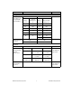
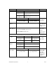
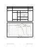
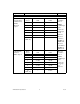
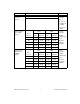
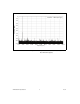
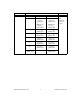
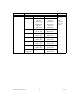
Table Of Contents
- NI PXI/PCI-5124 Specifications
- Contents
- Vertical
- Analog Input (Channel 0 and Channel 1)
- Figure 1. NI 5124 Frequency Response (Typical)
- Figure 2. NI 5124 Dynamic Performance, 50 W , 1 Vpk-pk Range, 262,144 Point FFT (Typical)
- Figure 3. Representation of NI 5124 Spectral Noise Density on 0.2 V Range, Noise Filter Enabled, 1 MW Input Impedance
- Figure 4. Representation of NI 5124 Spectral Noise Density on 0.2 V Range, Full Bandwidth, 50 W Input Impedance
- Analog Input (Channel 0 and Channel 1)
- Horizontal
- Trigger
- PFI 0 and PFI 1 (Programmable Function Interface, AUX Front Panel Connector)
- TClk Specifications
- Waveform Specifications
- Calibration
- Power
- Software
- Environment
- Safety, Electromagnetic Compatibility, and CE Compliance
- Physical
- Where to Go for Support

NI PXI/PCI-5124 Specifications 4 ni.com
DC Drift Range (V
pk-pk
) 50 Ω and 1 MΩ —
0.2, 0.4, 1, and 2 ±(0.057% of Input + 0.006% of FS
+100μV) per °C
4, 10, and
20 (1 MΩ only)
±(0.057% of Input + 0.006% of FS
+ 900 µV) per °C
AC Amplitude
Accuracy
50 Ω 1MΩ Within ±5 °C of
self-calibration
temperature
±0.06 dB
(±0.7%) at 50 kHz
±0.09 dB
(±1.0%) at 50 kHz
Crosstalk,
Typical
≤–85 dB at 10 MHz CH 0 to/from
CH 1, External
Trigger to CH 0
or CH 1
Sparkle Code
Rate, Typical
<300 ppt
*
with onboard clock or 200 MHz external clock
<3 ppt
*
with 150 MHz external clock
0 with 100 MHz external clock
Results based
on 2 × 10
12
samples
*
ppt = parts per
trillion (10
12
)
Bandwidth and Transient Response
Bandwidth
(–3 dB)
Range (V
pk-pk
) 50 Ω 1MΩ Filters off
*
135 MHz
above 40 °C
All ranges
except 0.2
150 MHz 145 MHz up to
40 °C
*
0.2 85 MHz 75 MHz
Rise/Fall Time,
Typical
Range (V
pk-pk
) 50 Ω and 1 MΩ Filters off
All ranges
except 0.2
2.4 ns
0.2 3.3 ns
Bandwidth
Limit Filters
Noise Filter Antialias Filter Only one filter
can be enabled
at any given
time. The
antialias filter
is enabled by
default.
20 MHz, typical
2-pole Bessel filter
60 MHz, typical
4-pole elliptical filter
Specification Val ue Comments