
user manual
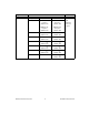
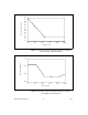
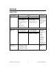
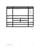
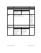

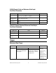
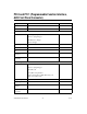
Table Of Contents
- NI PXI/PCI-5124 Specifications
- Contents
- Vertical
- Analog Input (Channel 0 and Channel 1)
- Figure 1. NI 5124 Frequency Response (Typical)
- Figure 2. NI 5124 Dynamic Performance, 50 W , 1 Vpk-pk Range, 262,144 Point FFT (Typical)
- Figure 3. Representation of NI 5124 Spectral Noise Density on 0.2 V Range, Noise Filter Enabled, 1 MW Input Impedance
- Figure 4. Representation of NI 5124 Spectral Noise Density on 0.2 V Range, Full Bandwidth, 50 W Input Impedance
- Analog Input (Channel 0 and Channel 1)
- Horizontal
- Trigger
- PFI 0 and PFI 1 (Programmable Function Interface, AUX Front Panel Connector)
- TClk Specifications
- Waveform Specifications
- Calibration
- Power
- Software
- Environment
- Safety, Electromagnetic Compatibility, and CE Compliance
- Physical
- Where to Go for Support

NI PXI/PCI-5124 Specifications 20 ni.com
PFI 0 and PFI 1 (Programmable Function Interface,
AUX Front Panel Connector)
Specification Value Comments
Connector 9-pin mini-circular DIN —
Direction Bi-directional —
As an Input (Trigger)
Destinations Start Trigger (Acquisition Arm)
Reference (Stop) Trigger
Arm Reference Trigger
Advance Trigger
—
Input Impedance 150 kΩ —
V
IH
2.0 V —
V
IL
0.8 V —
Maximum Input
Overload
–0.5 V, 5.5 V —
Maximum
Frequency
25 MHz —
As an Output (Event)
Sources Start Trigger (Acquisition Arm)
Reference (Stop) Trigger
End of Record
Done (End of Acquisition)
Probe Compensation (1 kHz, 50% duty cycle
square wave, PFI 1 only)
—
Output Impedance 50 Ω —
Logic Type 3.3 V CMOS —
Maximum Drive
Current
±24 mA —
Maximum
Frequency
25 MHz —