
user manual
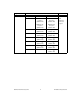
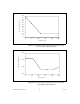
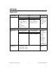
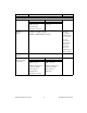

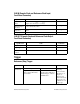
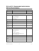
Table Of Contents
- NI PXI/PCI-5124 Specifications
- Contents
- Vertical
- Analog Input (Channel 0 and Channel 1)
- Figure 1. NI 5124 Frequency Response (Typical)
- Figure 2. NI 5124 Dynamic Performance, 50 W , 1 Vpk-pk Range, 262,144 Point FFT (Typical)
- Figure 3. Representation of NI 5124 Spectral Noise Density on 0.2 V Range, Noise Filter Enabled, 1 MW Input Impedance
- Figure 4. Representation of NI 5124 Spectral Noise Density on 0.2 V Range, Full Bandwidth, 50 W Input Impedance
- Analog Input (Channel 0 and Channel 1)
- Horizontal
- Trigger
- PFI 0 and PFI 1 (Programmable Function Interface, AUX Front Panel Connector)
- TClk Specifications
- Waveform Specifications
- Calibration
- Power
- Software
- Environment
- Safety, Electromagnetic Compatibility, and CE Compliance
- Physical
- Where to Go for Support

© National Instruments Corporation 15 NI PXI/PCI-5124 Specifications
External Sample Clock
Sources NI PXI-5124 NI PCI-5124 —
CLK IN (front panel
SMB connector)
PXI Star Trigger
(backplane connector)
CLK IN (front panel SMB
connector)
Frequency
Range
50 MHz to 210 MHz (CLK IN)
50 MHz to 80 MHz (PXI Star Trigger)
Divide by
n decimation
available where
1 ≤ n ≤ 65,535
For more
information
about Sample
Clock and
decimation,
refer to the
NI High-Speed
Digitizers Help.
Duty Cycle
Tolerance
45% to 55% —
Exported
Reference Clock
Destinations
NI PXI-5124 NI PCI-5124 —
CLK OUT (front panel
SMB connector)
PFI<0..1> (front panel
9-pin mini-circular
DIN connector)
PXI_Trig<0..7>
(backplane connector)
CLK OUT (front panel
SMB connector)
PFI<0..1> (front panel
9-pin mini-circular
DIN connector)
RTSI<0..7>
Specification Value Comments