
Deterministic Ethernet Expansion Chassis User's Guide

© National Instruments Corporation 37 NI 9144 User Guide and Specifications
one conversion in the future, at time t+1. The conversion code is listed in
Table 29.
Note The conversion rate for every channel must match the value of the conversion speed
control in 0x2002.
For example, the scan list entry 0x00000001FC indicates this scan stores at
address 1, and the next conversion is channel 2 at high-accuracy.
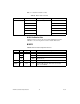
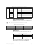
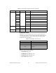
Table 30 contains the default scan list.
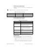
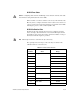
NI 9217 Calibration Data
The NI 9217 has four RTD channels that can measure 100 Ω RTD in 3-wire
and 4-wire mode. There is a 1 mA excitation current source per channel and
the module range is –500 Ω to 500 Ω. The resistance range specified in the
manual is 0 to 400 Ω. This range is tested and covers the temperature range
of –200 ºC to 850 ºC for the standard platinum RTD. The channel does not
read negative resistance.
Each channel has an associated LSB weight, which is the number of
Ω per bit, and an offset, which is the number of Ω per bit measured when
the inputs are grounded.
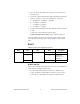
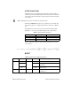
Table 29. NI 9217 Conversion Code
Bits Field
7:3 Conversion rate: 0b11111 = 31,
High-Accuracy
0b00010 = 2, High-Speed
2:1 Channel number
0 Reserved
Table 30. NI 9217 Scan List Format
Index Sub Type Value
0x2001 0 ARR:U32 5
1 4
2 0x0000 | 0xF8 | 0x02
3 0x0100 | 0xF8 | 0x04
4 0x0200 | 0xF8 | 0x06
5 0x0300 | 0xF8 | 0x00