DAQ 6527 User Manual Isolated Digital I/O Interface for PCI, PXI, and CompactPCI 6527 User Manual December 1999 Edition Part Number 322164A-01
Worldwide Technical Support and Product Information www.ni.
Important Information Warranty The 6527 device is warranted against defects in materials and workmanship for a period of one year from the date of shipment, as evidenced by receipts or other documentation. National Instruments will, at its option, repair or replace equipment that proves to be defective during the warranty period. This warranty includes parts and labor.
Contents About This Manual How To Use the Manual Set..........................................................................................ix Conventions ...................................................................................................................x Related Documentation..................................................................................................x Chapter 1 Introduction About the 6527 Device .......................................................................
Contents Solid-State Relay Outputs ............................................................................................. 3-9 Output Channels.............................................................................................. 3-9 Overcurrent Protection .................................................................................... 3-12 Power-on and Power-off Conditions............................................................... 3-12 Chapter 4 Device Overview Functional Overview ..
Contents Tables Table 3-1. Table 3-2. Port Functionality for 6527 Devices .....................................................3-3 Signal Descriptions for 6527 Device I/O Connectors ...........................3-5 Table 4-1. Table 4-2. Digital Filter Characteristics .................................................................4-4 Change Notification Example ...............................................................
About This Manual This manual describes the electrical and mechanical aspects of the 6527 devices, and contains information concerning their operation and programming. Unless otherwise noted, the text applies to all devices in the 6527 family, which includes the PCI-6527 and PXI-6527. How To Use the Manual Set The 6527 User Manual is one piece of the documentation set for your data acquisition system. You could have any of several types of manuals, depending on the hardware and software in your system.
About This Manual Conventions The following conventions appear in this manual: <> Angle brackets that contain numbers separated by an ellipsis represent a range of values associated with a bit or signal name—for example, DIG+0.<3..0>. ♦ The ♦ symbol indicates that the text following it applies only to a specific product, a specific operating system, or a specific software version. This icon denotes a note, which alerts you to important information.
1 Introduction This chapter describes the 6527 devices; lists what you need to get started, software programming choices, and optional equipment; describes custom cabling options; and explains how to unpack your board. About the 6527 Device Thank you for purchasing a National Instruments 6527 device. The 6527 devices are 48-bit, parallel, isolated digital I/O interfaces for PCI bus computers and PXI or Compact PCI chassis. The 6527 devices offer 48 channels of isolated digital data acquisition.
Chapter 1 Introduction Using PXI with CompactPCI Using PXI-compatible products with standard CompactPCI products is an important feature provided by the PXI Specification, Revision 1.0. If you use a PXI-compatible plug-in device in a standard CompactPCI chassis, you will be unable to use PXI-specific functions, but you can still use the basic plug-in device functions. All 6527 device functions are available in a CompactPCI chassis.
Chapter 1 Introduction Unpacking Your 6527 device is shipped in an antistatic package to prevent electrostatic damage to the board. Electrostatic discharge can damage several components on the board. To avoid such damage in handling the board, take the following precautions: • Ground yourself via a grounding strap or by holding a grounded object. • Touch the antistatic package to a metal part of your computer chassis before removing the board from the package.
Chapter 1 Introduction ComponentWorks contains tools for data acquisition and instrument control built on NI-DAQ driver software. ComponentWorks provides a higher-level programming interface for building virtual instruments through standard OLE controls and DLLs. With ComponentWorks, you can use all of the configuration tools, resource management utilities, and interactive control utilities included with NI-DAQ.
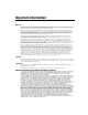
Chapter 1 LabVIEW, LabWindows/CVI, or ComponentWorks Introduction Conventional Programming Environment NI-DAQ Driver Software DAQ or SCXI Hardware Personal Computer or Workstation Figure 1-1.
Chapter 1 Introduction Custom Cabling National Instruments offers cables and accessories for you to prototype your application or to use if you frequently change board interconnections. If you want to develop your own cable, note that the 6527 device uses a 100-pin female cable header. AMP Corporation part number 749621-9 may be used for the mating connector.
Installation and Configuration 2 This chapter describes how to install and configure your 6527 device. Software Installation Note Install your software before you install your 6527 device. Refer to the appropriate release notes indicated below for specific instructions on the software installation sequence. If you are using NI-DAQ, refer to your NI-DAQ release notes. Find the installation section for your operating system and follow the instructions given there.
Chapter 2 Installation and Configuration ♦ 3. Remove the expansion slot cover on the back panel of the computer. 4. Touch a metal part inside your computer to discharge any static electricity that might be on your clothes or body. 5. Insert the PCI-6527 in a 5 V PCI slot. It may be a tight fit, but do not force the device into place. 6. Screw the mounting bracket of the PCI-6527 to the back panel rail of the computer. 7. Visually verify the installation. 8.
3 Signal Connections This chapter describes the pin arrangement, signal names, and signal connections on your 6527 device. Connections that exceed any of the maximum ratings of input or output signals on your 6527 device can damage the board and your computer. The description of each signal in this chapter includes information about maximum input ratings. National Instruments is not liable for any damages resulting from signal connections that exceed these maximum ratings.
Chapter 3 Signal Connections Note For input ports, connect the higher voltage to the DIG+ pin and the lower voltage to the DIG– pin. For output ports, you can connect signals to the two pins of each line without regard to which voltage is higher. The output lines consist of solid-state relays and act as bidirectional switches. DIG+2.7 DIG–2.7 DIG+2.6 DIG–2.6 DIG+2.5 DIG–2.5 DIG+2.4 DIG–2.4 DIG+2.3 DIG–2.3 DIG+2.2 DIG–2.2 DIG+2.1 DIG–2.1 DIG+2.0 DIG–2.0 DIG+1.7 DIG–1.7 DIG+1.6 DIG–1.6 DIG+1.5 DIG–1.
Chapter 3 Signal Connections Table 3-1 shows the functionality of each port. Table 3-1. Port Functionality for 6527 Devices Port Function 0 Input 1 Input 2 Input 3 Output with readback 4 Output with readback 5 Output with readback Cable Assembly Connectors The optional R1005050 cable assembly you can use with the 6527 device is an assembly of two 50-pin cables and three connectors. Both cables are joined to a single connector on one end and to individual connectors on the free ends.
Chapter 3 Signal Connections DIG+2.7 DIG+2.6 DIG+2.5 DIG+2.4 DIG+2.3 DIG+2.2 DIG+2.1 DIG+2.0 DIG+1.7 DIG+1.6 DIG+1.5 DIG+1.4 DIG+1.3 DIG+1.2 DIG+1.1 DIG+1.0 DIG+0.7 DIG+0.6 DIG+0.5 DIG+0.4 DIG+0.3 DIG+0.2 DIG+0.1 DIG+0.0 +5 V 1 3 5 7 9 11 13 15 17 19 21 23 25 27 29 31 33 35 37 39 41 43 45 47 49 2 4 6 8 10 12 14 16 18 20 22 24 26 28 30 32 34 36 38 40 42 44 46 48 50 DIG–2.7 DIG+5.7 DIG–2.6 DIG+5.6 DIG–2.5 DIG+5.5 DIG–2.4 DIG+5.4 DIG–2.3 DIG+5.3 DIG–2.2 DIG+5.2 DIG–2.1 DIG+5.1 DIG–2.
Chapter 3 Signal Connections I/O Connector Signal Descriptions Table 3-2 lists the signal descriptions for the 6527 device I/O connector pins. Table 3-2. Signal Descriptions for 6527 Device I/O Connectors Pin Signal Name Description 33, 35, 37, 39, 41, 43, 45, 47 DIG+0.<7..0> Isolated input port 0, positive terminals—Take measurements at these terminals. These terminals should be positive relative to their corresponding DIG– lines.
Chapter 3 Signal Connections Table 3-2. Signal Descriptions for 6527 Device I/O Connectors (Continued) Pin Signal Name Description 83, 85, 87, 89, 91, 93, 95, 97 DIG+3.<7..0> Isolated output port 3, first terminals—Each of these is the first of two terminals of a bidirectional solid-state relay. A logic low (data bit of 0) closes the relay. 84, 86, 88, 90, 92, 94, 96, 98 DIG–3.<7..
Chapter 3 Signal Connections Isolation Voltages The positive and negative (DIG+ and DIG–) terminals of each channel are isolated from the other input and output channels, from the +5 V and GND pins, and from the computer power supply. Isolation barriers provide isolation up to 60 VDC or 30 VAC (42 V peak) between any two terminals, except between the two terminals making up a single digital I/O channel.
Chapter 3 Signal Connections Sensing DC Voltages When you apply a DC voltage of at least 2 V across the two input terminals, the 6527 device registers a logic high for that input. If no voltage is present (a voltage difference of 1 V or less), the 6527 device registers a logic low for that input. DC voltages between 1 V and 2 V are invalid and register an indeterminate value. Thus, you can use the 6527 device to sense a wide range of DC signals—from TTL logic levels to DC power supply levels up to 28 V.
Chapter 3 Signal Connections Reducing the Forward Current for High Voltages As input voltage increases above 5 V, the input current drawn by the 6527 (forward current IF) also rises. At 24 V, for example, current is approximately (24 V – 1.5 V)/3 kΩ = 7.5 mA per line. If you wish to reduce the current and power the 6527 draws—to reduce the impact on a circuit you are monitoring, for example—you can add another resistor in series with the 3 kΩ current-limiting resistor on the 6527.
Chapter 3 Signal Connections 6527 +5 V If LH1546 390 Ω DIG+ RS 35 Ω + Supply – Load Digital Logic DIG– Isolated Ground Isolation a. Sinking Current 6527 +5 V LH1546 390 Ω DIG+ 35 Ω + Supply – If Digital Logic DIG– Isolation RS Load Isolated Ground b. Sourcing Current Figure 3-5. Signal Connections for Solid-State Relays Writing a 0 (logic low) to an output bit closes the relay, and writing a 1 (logic high) opens the relay.
Chapter 3 Signal Connections Figure 3-6 shows a signal connection example for both sinking and sourcing current. The example shows a TTL-level application with a supply voltage of +5 V. The 6527 provides sink current when the relay is closed. Resistor RL provides source current when the relay is open. When the relay is open, little current flows through the resistor and the output voltage is close to 5 V, a logic high.
Chapter 3 Signal Connections Overcurrent Protection The 6527 device outputs include circuitry to protect them from currents over the specified range. When excessive current flows through the relay, the relay increases resistance. Once the current level drops back under the specified range, the relays return to normal operation.
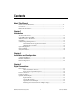
4 Device Overview This chapter contains a functional overview of the 6527 device and explains the operation of each functional unit. The digital filter and change detection options are also described. Functional Overview The block diagram in Figure 4-1 illustrates the key functional components of your 6527 device.
Device Overview Port 0 Isolation Port 1 Isolation PCI or PXI Bus PCI MITE Interface Digital I/O Circuitry (FPGA) Port 2 Isolation EEPROM Port 3 Isolation Port 4 Isolation EEPROM Port 5 Isolation Port 0 16 Port 1 16 Port 2 16 Port 3 I/O Connector Chapter 4 16 Port 4 16 Port 5 16 Figure 4-1. 6527 Block Diagram PCI Interface Circuitry Your 6527 board uses the PCI MITE ASIC to communicate with the PCI bus. The PCI MITE was designed by National Instruments specifically for data acquisition.
Chapter 4 • Device Overview Input ports – Read – Apply digital filtering (software programmable) – Detect changes on selected lines (software programmable) Table 3-1, Port Functionality for 6527 Devices, contains a summary of port functions. Optical Isolation Circuitry The digital input ports of a 6527 device are optically isolated using Infineon IL55B optocouplers. Each IL55B provides optical isolation for one channel of input.
Chapter 4 Device Overview Table 4-1. Digital Filter Characteristics Pulse Width Passed Pulse Width Blocked Filter Interval Low Pulse High Pulse Low Pulse High Pulse tinterval tinterval + 100 µs tinterval tinterval /2 (tinterval /2) – 100 µs You can enable filtering on as many input lines as you wish. All filtered lines share the same timing interval. The interval ranges from 100 ns to 100 ms.
Chapter 4 Device Overview Figure 4-2 shows a filter configuration with an 800 ns filter interval (400 ns filter clock). In practice, a much slower filter interval is recommended. In periods A and B the filter blocks the glitches because the external signal does not remain steadily high from one filter clock to the next. In period C, the filter passes the transition because the external signal does remain steadily high.
Chapter 4 Device Overview If you anticipate noisy or rapidly changing input lines, use digital filtering to reduce the changes to a manageable number; excessive notifications can hurt system performance. For example, if you want to limit the rate of notifications (and interrupts) to a maximum of one change per line every 10 ms, set a filter interval of 10 ms. Table 4-2 shows configuring change notification for five bits of one port.
A Specifications This appendix lists the specifications for the 6527 devices. These specifications are typical at 25 °C unless otherwise noted. Digital I/O PCI/PXI-6527......................................... 24 optically isolated digital input channels and 24 solid-state relay output channels Isolated Inputs Number of input channels ...................... 24, each with its own ground reference isolated from other channels Max input voltage ..................................
Appendix A Specifications for Relay Outputs Number of channels................................24, each with two terminals that are isolated from other channels Relay type ...............................................Normally open form A solid-state relays Max switching voltage AC....................................................30 V RMS (42 V peak) DC....................................................60 VDC Max switching capacity ..........................120 mA1 Common-mode isolation ...............
Appendix A Specifications for Physical Dimensions (not including connectors) PCI-6527 ......................................... 17.5 × 10.7 cm (6.9 × 4.2 in.) PXI-6527......................................... 16 × 10 cm (6.3 × 3.9 in.) I/O connector.......................................... 100-pin keyed female ribbon-cable connector Environment Operating temperature............................ 0 to 50 °C Storage temperature ............................... –20 to 70 °C Relative humidity .................
Technical Support Resources B This appendix describes the comprehensive resources available to you in the Technical Support section of the National Instruments Web site and provides technical support telephone numbers for you to use if you have trouble connecting to our Web site or if you do not have internet access. NI Web Support To provide you with immediate answers and solutions 24 hours a day, 365 days a year, National Instruments maintains extensive online technical support resources.
Appendix B Technical Support Resources Software-Related Resources • Instrument Driver Network—A library with hundreds of instrument drivers for control of standalone instruments via GPIB, VXI, or serial interfaces. You also can submit a request for a particular instrument driver if it does not already appear in the library. • Example Programs Database—A database with numerous, non-shipping example programs for National Instruments programming environments.
Glossary Prefix Meanings Value n- nano- 10 –9 µ- micro- 10 – 6 m- milli- 10 –3 k- kilo- 10 3 Numbers/Symbols ° degrees – negative of, or minus Ω ohms / per % percent ± plus or minus + positive of, or plus +5 V +5 Volts signal A A amperes AC alternating current ANSI American National Standards Institute ASIC Application-Specific Integrated Circuit—a proprietary semiconductor component designed and manufactured to perform a set of specific functions © National Instrument
Glossary C C Celsius CAT I installation category (overvoltage category) I—equipment for which measures are taken to limit transient overvoltages to an appropriate low level. Examples include signal-level, telecommunications, and electronic equipment with transient overvoltages smaller than local-level mains supplies.
Glossary I IIH current, input high IIL current, input low in.
Glossary O optocoupler a device that transfers electrical signals by utilizing light waves to provide coupling with electrical isolation between input and output optical isolation the technique of using an optocoupler to transfer data without electrical continuity, to eliminate high-potential differences and transients P PCI Peripheral Component Interconnect—a high-performance expansion bus architecture originally developed by Intel to replace ISA and EISA.
Glossary T TTL transistor-transistor logic, or 5 V digital voltage levels originally used with transistor-transistor logic typ typical V V volts Vcc supply voltage; for example, the voltage a computer supplies to its plug-in devices VDC volts direct current VI virtual instrument—a combination of hardware and/or software elements, typically used with a PC, that has the functionality of a classic standalone instrument VIH volts, input high VIL volts, input low VIN input voltage VOH volts,
Index Numbers CompactPCI, using with PXI, 1-2 ComponentWorks software, 1-4 configuration, 2-2 connector. See I/O connector.
Index E L environment specifications, A-3 equipment, optional, 1-5 LabVIEW software, 1-3 LabWindows/CVI software, 1-3 F M filtering. See digital filtering. forward current for high voltages, reducing, 3-8 to 3-9 fuse, self-resetting, 3-6 manual. See documentation.
Index power-on and power-off conditions, 3-12 software installation, 2-1 software programming choices, 1-3 to 1-5 National Instruments application software, 1-3 to 1-4 NI-DAQ driver software, 1-4 to 1-5 software-related resources, B-2 solid-state relay outputs, 3-9 to 3-12 output channels, 3-9 to 3-11 driving a load (example), 3-9 to 3-10 sinking and sourcing current (example), 3-11 overcurrent protection, 3-12 power-on and power-off conditions, 3-12 specifications, A-2 specifications, A-1 to A-3 digital I