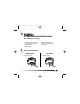
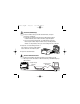
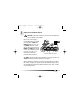
fpoint cd.qxd 11/13/00 1:23 PM Page 1 FP-1600 FieldPoint Quick Start Guide What You Need to Get Set Up · Network Module · Mounting Hardware (DIN rail or panel mount accessory) · Terminal Base(s) · I/O Module(s) 1 · Power Supply · FieldPoint Software CD · Accessories: Ethernet cable, screwdriver Install the Network Module DIN Rail Mount A. Unlock rail clip. Panel Mount A. Unlock rail clip.
fpoint cd.qxd 11/13/00 1:23 PM DIN Rail Mount NOTE: Do not use spliced DIN rails. Use only a single DIN rail. Page 2 Panel Mount B. Snap panel mount accessory (which you can order separately) onto module. B. Hook lip on back of module onto top of DIN rail, press down, and snap into place. C. Lock rail clip. C. Slide module into position and lock rail clip. 2 D. Use template that came with your accessory to drill pilot holes and mount module onto panel using accessory.
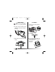
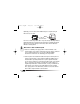
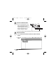
fpoint cd.qxd 2 11/13/00 1:23 PM Page 3 Install the Terminal Base(s) CAUTION: Terminal bases must be connected to the network module before applying power to the module. Do not connect or disconnect terminal bases while power is applied to the network module. DIN Rail Mount A. Unlock rail clip. Panel Mount A. Use template that came with your accessory to drill pilot holes. B. Connect terminal base to network module connector, being careful not to bend any connector pins. B. Press base onto rail. C.
fpoint cd.qxd 11/13/00 1:23 PM DIN Rail Mount C. Slide into position and lock the rail clip. Be careful not to bend any pins. Page 4 Panel Mount D. Repeat for each terminal base, up to nine for each network module in most cases. You can use one or two extender cables (which you can order separately) if your FieldPoint bank is too long for your available space. E. Place protective cover on last base. D. Repeat for each terminal base, up to nine for each network module in most cases.
fpoint cd.qxd 3 11/13/00 1:23 PM Page 5 Install the I/O Module(s) It does not matter where you install each I/O module, except for these types of situations: · If you plan to cascade power between any I/O modules using the V and C terminals, those modules should be grouped together. · For more accurate measurements, you might want to locate any thermocouple modules away from heat sources, including network modules or relay modules, unless you are mounting them on an FP-TB-3. A.
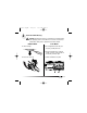
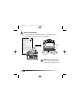
fpoint cd.qxd 11/13/00 1:23 PM Page 6 Optionally, you can connect an FP-1600 directly to a computer using an Ethernet crossover cable. Cross-Over Cable Do not use a cable longer than 100 m. If you are using a 100 Mbps Ethernet, National Instruments recommends using a Category 5 shielded twisted-pair Ethernet. If you need to build your own cable, refer to the FP-1600 User Manual for cabling details. 5 Wire Power to Your FieldPoint System A.
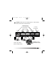
fpoint cd.qxd 11/13/00 1:23 PM Page 7 CAUTION: Cascading power from neighboring bases or network modules defeats isolation between cascaded modules. Separate Power Supply (Recommended) No External Power Required Cascaded Power (Reduces Isolation) FP-1600 Power Supply FP-AI-100 FP-AO-200 FP-RLY-420 FP-TC-120 Power Supply 15 16 V Shades of gray indicate different voltage potentials. 31 32 C V 1 2 3 C 17 18 CAUTION: Cascading power defeats isolation.
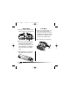
fpoint cd.qxd 6 11/13/00 1:23 PM Page 8 Connect to Field Devices Use each I/O module’s operating instructions, or the diagram under its removable label, to help you connect your field devices. FP-AI-110 8 Channel, 16-Bit Analog Input Module Highlights FP-AI-110 To Power Supply Overview h.
fpoint cd.qxd 7 11/13/00 1:23 PM Page 9 Power Up Your FieldPoint System CAUTION: Terminal bases must be connected to the FP-1600 before power is applied to the FP-1600. Plug in each power supply to your FieldPoint bank. You should see all except the STATUS and PROCESS LEDs flash once, and the POWER LED come on and stay on. After a few seconds, the POWER and READY LEDs should be lit on each I/O module. If this is not the case, refer to your FP-1600 user manual for troubleshooting instructions.
fpoint cd.qxd 8 11/13/00 1:24 PM Page 10 Install the FieldPoint Software A. Close all other applications. If you plan to install National Instruments development software such as Lookout, LabVIEW, or Measurement Studio, install them before you install the FieldPoint software. B. Insert the FieldPoint software CD and follow the onscreen instructions. 9 Verify the Installation A. Select Start»Programs»National Instruments FieldPoint»FieldPoint Explorer. B.
fpoint cd.qxd 11/13/00 1:24 PM Page 11 C. In the Comm Resource Configuration dialog box, select Ethernet as the Type. D. Click Browse, select the FP-1600, and click the Device Properties button.
fpoint cd.qxd 11/13/00 1:24 PM Page 12 E. In the FP-1600 Properties box, enter values for the IP address, Subnet mask, and Time server IP. You might also want to enter a comment to help you identify the FP-1600 module. • IP address is the address of the FP-1600 on the network. • Subnet mask is the mask that is applied to the IP address that the device uses to find other devices on the Ethernet network (255.255.255.0 is the most common).
fpoint cd.qxd 11/13/00 1:24 PM Page 13 If your modules are not listed, check the cable and connections and make sure the modules are all powered on. If you still have problems, refer to your FP-1600 user manual for troubleshooting information. I. Select an input module and click on the start monitoring button to view live data. J. Select an output channel and click on the write button outputs. to change K. Select File»Save.
fpoint cd.qxd 11/13/00 1:24 PM Page 14 10 Configure I/O Modules A. Right-click on the device name in FieldPoint Explorer and select Edit this Device from the pop-up menu. B. Click on the Channel Configuration button to bring up the Channel Configuration dialog box. C. Select the type of channel to show, then select the channel(s) that you want to change. To select more than one channel, uncheck the One channel at a time box. NOTE: Configuration options are module-dependent.
fpoint cd.qxd 11/13/00 1:24 PM Page 15 D. Set the range and output values of the selected channel(s). E. Set the attributes for the selected channel(s) by selecting the attribute and entering the desired value. F. Send commands to the selected channel(s) by choosing a command and value and clicking on Send. G. Repeat this procedure for each channel you want to configure. H. Click on the OK button when you are finished, or click on the Apply button to save the changes and continue to configure channels.
fpoint cd.qxd 11/13/00 1:24 PM 11 Where to Go from Here Page 16 After you get your hardware up and running, you might want to implement features such as power-up defaults or network watchdog settings. Refer to your FP-1600 user manual or online help for information about features, configuration, application development, and troubleshooting.
fpoint cd.qxd 11/13/00 1:24 PM Page 17 FP-1600 Specifications Network interface . . . . . . . . . . . . . . . . . . . . 10BaseT and 100BaseTX Ethernet Compatibility. . . . . . . . . . . . . . . . . . . . . . . . IEEE 802.3 Communications rate . . . . . . . . . . . . . . . . . 10 Mbps, 100 Mbps, autonegotiated Cabling distance . . . . . . . . . . . . . . . . . . . . . 100 m Power supply range . . . . . . . . . . . . . . . . . . 11 to 30 VDC Power consumption . . . . . . . . . . . . . . . . . . 7 W + 1.
fpoint cd.qxd 11/13/00 1:24 PM Page 18 Mechanical Dimensions Dimensions are given in inches [millimeters]. 4.22 [107.19] 4.31 [109.5] 3.60 [91.
fpoint cd.qxd 11/13/00 1:24 PM Page 20 United States 512 795-8248 Australia 03 9879 5166, Austria 0662 45 79 90 0, Belgium 02 757 00 20, Brazil 011 284 5011, Canada (Calgary) 403 274 9391, Canada (Ontario) 905 785 0085, Canada (Québec) 514 694 8521, China 0755 3904939, Denmark 45 76 26 00, Finland 09 725 725 11, France 01 48 14 24 24, Germany 089 741 31 30, Greece 30 1 42 96 427, Hong Kong 2645 3186, India 91805275406, Israel 03 6120092, Italy 02 413091, Japan 03 5472 2970, Korea 02 596 7456, Mexico (D.