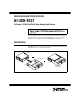
USER GUIDE AND SPECIFICATIONS NI USB-9237 4-Channel, 24-Bit Half/Full-Bridge Analog Input Device This user guide describes how to use the National Instruments USB-9237 and lists the device specifications. The NI USB-9237 provides a USB interface for four channels of 24-bit half/full-bridge analog input. Introduction The NI USB-9237 consists of two components: an NI 9237 module and an NI USB-9162 carrier, as shown in Figure 1.
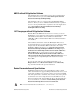
Dimensions Figure 2 shows the NI USB-9237 device dimensions. Hi-Speed USB Carrier 123.67 mm (4.869 in.) 120.68 mm (4.751 in.) 121.28 mm (4.775 in.) NI USB-9162 118.29 mm (4.567 in.) 88.11 mm (3.469 in.) 25.08 mm (0.988 in.) Figure 2. NI USB-9237 Device in Millimeters (Inches) Safety Guidelines Operate the NI USB-9237 only as described in these operating instructions.
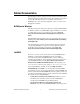
Related Documentation Each application software package and driver includes information about writing applications for taking measurements and controlling measurement devices. The following references to documents assume you have NI-DAQmx 8.7 or later, and where applicable, version 7.1 or later of the NI application software.
• Taking Measurements—Contains the conceptual and how-to information you need to acquire and analyze measurement data in LabVIEW, including common measurements, measurement fundamentals, NI-DAQmx key concepts, and device considerations. LabWindows/CVI The Data Acquisition book of the LabWindows/CVI Help contains measurement concepts for NI-DAQmx.
ANSI C without NI Application Software The NI-DAQmx Help contains API overviews and general information about measurement concepts. Select Start»All Programs»National Instruments»NI-DAQ»NI-DAQmx Help. The NI-DAQmx C Reference Help describes the NI-DAQmx Library functions, which you can use with National Instruments data acquisition devices to develop instrumentation, acquisition, and control applications. Select Start»All Programs»NationalInstruments»NI-DAQ» NI-DAQmx C Reference Help. .
Training Courses If you need more help getting started developing an application with NI products, NI offers training courses. To enroll in a course or obtain a detailed course outline, refer to ni.com/training. Technical Support on the Web For additional support, refer to ni.com/support or zone.ni.com. Installing the Software Software support for the NI USB-9237 for Windows Vista/XP/2000 is provided by NI-DAQmx. The DAQ Getting Started Guide, which you can download at ni.
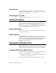
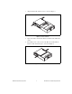
3. Align the I/O module with the carrier, as shown in Figure 3. Figure 3. Module Installation 4. Squeeze the latches and insert the NI 9237 module into the USB-9162 carrier. 5. Press firmly on the connector side of the NI 9237 module until the latches lock the module into place, as shown in Figure 4. Figure 4.
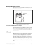
Mounting the NI USB-9237 to a Panel Threaded inserts are located in the NI USB-9237 for mounting it to a panel. Refer to Figure 5 for dimensions. 85.7 mm (3.37 in.) 72.2 mm (2.84 in.) Threaded Insert M3 x 0.5 8.5 mm (0.34 in.) Max Depth 76.1 mm (3.00 in.) Figure 5. Module Dimensions in Millimeters (Inches) Connecting the NI USB-9237 to a Computer Plug one end of the USB cable into the NI USB-9237 and the other end into an available USB port on the computer.
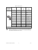
Table 1. LED State/Device Status LED State Device Status Not lit Device not connected or in suspend. On, not blinking Device connected, but no module installed. Single-blink Operating normally. Double-blink Connected to USB Full-Speed port. Device performance might be affected. Refer to the Specifications section for more information. Quadruple-blink Device error. Refer to ni.com/support.
Table 2.
3 2 4 1 1 EX– 2 EX+ 3 EX+ 4 EX– Figure 6. Four Position External Excitation Voltage Source Connection Connecting Loads to the NI USB-9237 Refer to Figure 7 for an illustration of how to connect full and half bridges to the NI USB-9237. RS+ EX+ AI+ AI–* 1 2 EX– SC SC T+ TEDS 1 RS– * When you connect a half bridge T– The dotted line indicates that the full bridge is optional while the half bridge is required. to the NI USB-9237, the AI– signal is not connected.
Completion Accessories for more information about these accessories and how to purchase them. Wiring TEDS Channels Ensure that neither the TEDS data (T+) nor the TEDS return (T–) is tied in common to any AI signals on the NI USB-9237. Visit ni.com/info and enter the info code rdteds for information about TEDS sensors. NI USB-9237 Connection Options Wiring resistance can create errors in bridge circuits.
As shown in Figure 8, the actual bridge excitation voltage is smaller than the voltage at the EX+ and EX– leads. If remote sensing of the actual bridge voltage is not used, the resulting gain error is 2 R lead ----------------- R bridge for full-bridge sensors, and R R bridge lead ----------------- for half-bridge sensors.
Excitation Voltages Although the sensor industry does not recognize a single standard excitation voltage level, excitation voltage levels of between 2.5 V and 10 V are common. You can program the NI USB-9237 to supply 2.5 V, 3.3 V, 5 V, or 10 V of excitation voltage, and the module can provide up to 150 mW of excitation power. Unless you supply external excitation voltage, National Instruments recommends that you set the excitation voltage to a value that keeps the total power below 150 mW.
Each channel on the NI USB-9237 has an independent 24-bit ADC and input amplifier that enable you to sample signals from all four channels simultaneously. The NI USB-9237 also includes filters to prevent aliasing. The filters on the NI USB-9237 filter according to the sampling rate. Understanding NI USB-9237 Filtering The NI USB-9237 uses a combination of analog and digital filtering to provide an accurate representation of desirable signals while rejecting out-of-band signals.
Stopband The filter significantly attenuates all signals above the stopband frequency. The primary goal of the filter is to prevent aliasing. Therefore, the stopband frequency scales precisely with the data rate. The stopband rejection is the minimum amount of attenuation applied by the filter to all signals with frequencies that would be aliased into the alias-free bandwidth.
Overvoltage protection between any two terminals..................... ± 30 V Accuracy Percent of Reading (Gain Error) Percent of Range (Offset Error)† Calibrated max (0 to 60 °C) 0.20% 0.25% Calibrated typ (25 °C, ±5 °C) 0.05% 0.05% Uncalibrated max (0 to 60 °C) 0.60% 0.35% 0.20 0.1% Error* Uncalibrated typ (25 °C, ±5 °C) * Excluding offset null or shunt calibration. † Range equals 25 mV/V. Gain drift ................................................ 10 ppm/°C max Offset drift 2.
Stopband Frequency ........................................0.55 · fs Rejection..........................................100 dB Alias-free bandwidth ..............................0.45 · fs Oversample rate ......................................64 · fs Rejection at oversample rate1 50 kS/s ......................................90 dB @ 3.2 MHz 10 kS/s ......................................60 dB @ 640 kHz Common-mode voltage All signals to earth ground ..............
Crosstalk 1 kHz............................................... 110 dB 10 kHz............................................. 100 dB Shunt calibration Resistance ....................................... 100 kΩ Resistor accuracy 25 °C ........................................ ± 110 Ω 0 to 60 °C................................. ± 200 Ω Excitation Internal voltage ............................... 2.5 V, 3.3 V, 5.0 V, 10.0 V Internal power ................................. 150 mW max External voltage .................
Isolation Channel-to-channel..........................No isolation between channels Channel-to-earth ground Continuous ...............................60 VDC, Measurement Category I Withstand .................................1,000 Vrms, verified by a 5 s dielectric withstand test Measurement Category I is for measurements performed on circuits not directly connected to the electrical distribution system referred to as MAINS voltage. MAINS is a hazardous live electrical supply system that powers equipment.
Operating humidity (IEC 60068-2-56) ................................... 10 to 90% RH, noncondensing Storage humidity (IEC 60068-2-56) ................................... 5 to 95% RH, noncondensing Maximum altitude .................................. 2,000 m Pollution Degree (IEC 60664) ...............
Environmental Management National Instruments is committed to designing and manufacturing products in an environmentally responsible manner. NI recognizes that eliminating certain hazardous substances from our products is beneficial not only to the environment but also to NI customers. For additional environmental information, refer to the NI and the Environment Web page at ni.com/environment.
Where to Go for Support The National Instruments Web site is your complete resource for technical support. At ni.com/support you have access to everything from troubleshooting and application development self-help resources to email and phone assistance from NI Application Engineers. National Instruments corporate headquarters is located at 11500 North Mopac Expressway, Austin, Texas, 78759-3504. National Instruments also has offices located around the world to help address your support needs.