USER GUIDE AND SPECIFICATIONS NI cDAQ-9172 This user guide describes how to use the National Instruments cDAQ-9172 chassis and lists specifications. For an interactive demonstration of how to install the NI cDAQ-9172, go to ni.com/info and enter daqinstall. The NI cDAQ-9172 is an eight-slot USB chassis designed for use with C Series I/O modules. The NI cDAQ-9172 chassis is capable of measuring a broad range of analog and digital I/O and sensors using a Hi-Speed USB 2.0 interface.
Safety Guidelines Operate the NI cDAQ-9172 chassis only as described in this user guide. Note Because some C Series I/O modules may have more stringent certification standards than the NI cDAQ-9172 chassis, the combined system may be limited by individual component restrictions. Refer to the Using the NI cDAQ-9172 section of this document for more details. Caution The NI cDAQ-9172 chassis is not certified for use in hazardous locations. Hot Surface This icon denotes that the component may be hot.
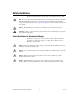
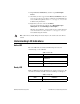
Installing the NI cDAQ-9172 Figure 2 shows the dimensions of the NI cDAQ-9172 chassis. 19.0 mm (0.75 in.) 165.1 mm (6.50 in.) NATIONAL INSTRUMENTS 36.4 mm (1.43 in.) NI cDAQ-9172 88.1 mm (3.50 in.) ON Ready 59.6 mm (2.35 in.) Active 1 2 3 4 5 6 7 8 OFF 51.7 mm (2.04 in.) 11-30 VDC 15 W 4.10 mm (0.16 in.) 254.0 mm (10.00 in.) 23.7 mm (0.94 in.) 44.1 mm (1.74 in.) 20.3 mm (0.80 in.) 25.0 mm (0.98 in.) 53.8 mm (2.12 in.) 44.1 mm (1.74 in.) 63.1 mm (2.49 in.) 46.0 mm (1.81 in.) 24.
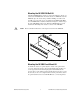
Mounting the NI cDAQ-9172 You can mount the NI cDAQ-9172 chassis using a desktop, a 35 mm DIN-Rail, or a panel mount accessory kit. For accessory ordering information, refer to ni.com. Caution Your installation must meet the following requirements: • Allows 25.4 mm (1 in.) of clearance above and below the NI cDAQ-9172 chassis for air circulation. • Allows 50.8 mm (2 in.) of clearance in front of modules for common connector cabling, such as the 10-terminal detachable screw terminal connector.
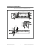
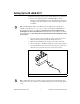
Mounting the NI 9910 DIN-Rail Kit The NI 9910 DIN-Rail kit contains one clip for mounting the chassis on a standard 35 mm DIN-Rail. To mount the chassis on a DIN-Rail, fasten the DIN-Rail clip to the chassis using a number 2 Phillips screwdriver and two M4 × 16 screws. The screws are included in the DIN-Rail kit. Make sure the DIN-Rail kit is installed as illustrated in Figure 4, with the larger lip of the DIN-RAIL positioned up.
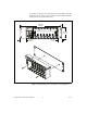
screws. Figure 5 illustrates the panel dimensions and installation on the NI cDAQ-9172 chassis. Refer to the documentation included with the NI 9905 shipping kit for more detailed dimensions. 330.2 mm (13.00 in.) NATIONAL INSTRUMENTS NI cDAQ-9172 ON Ready Active 1 2 3 4 5 6 7 OFF 8 88.1 mm (3.47 in.) 11-30 VDC 15 W 48.1 mm (1.90 in.) 28.1 mm (1.11 in.) Figure 5. Panel Mount Dimensions and Installation on the NI cDAQ-9172 NI cDAQ-9172 User Guide and Specifications 6 ni.
Setting Up the NI cDAQ-9172 Complete the following steps to prepare the NI cDAQ-9172 chassis for use: 1. Before connecting the hardware, install NI-DAQmx software, VI Logger, and the NI-DAQ Device Documentation Browser. Refer to the DAQ Getting Started Guide for more information about software installation. The NI-DAQmx software is included on the CD shipped with your kit and is available for download at ni.com/support.
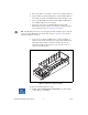
5. Remove the plastic cover from the connector in any empty module slot. 6. Squeeze both C Series I/O module latches, insert the I/O module into the module slot, and press until both latches lock the module in place. 7. Connect the NI cDAQ-9172 chassis with the supplied USB cable to any available USB port on your computer. 8. Connect the power source to the NI cDAQ-9172 chassis. The NI cDAQ-9172 chassis requires an external power supply that meets the specifications in the Power Requirements section.
12. Expand Devices and Interfaces, and then expand NI-DAQmx Devices. 13. Check that your device appears under Devices and Interfaces. If your device does not appear, press to refresh the view in MAX. If your device is still not recognized, refer to ni.com/support/install for troubleshooting information. 14. Right-click your device and select Self-Test. If you need help during the self-test, select Help»Help Topics» NI-DAQmx and click MAX Help for NI-DAQmx.
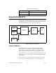
Table 2. Ready LED (Continued) LED Definition Green Full-Speed (12 Mbit/sec) Off USB connection is not established Using the NI cDAQ-9172 The cDAQ system consists of three parts: C Series I/O modules, the cDAQ module interface, and the USB-STC2. These components digitize signals, perform D/A conversions to generate analog output signals, measure and control digital I/O signals, and provide signal conditioning. C Series I/O Module cDAQ Module Interface USBSTC2 USB 2.
wiring connections directly from the C Series I/O modules to your sensors/actuators. In most cases, the C Series I/O modules provide isolation from channel-to-earth ground. For more information about which C Series I/O modules are compatible with the NI cDAQ-9172 chassis, refer to the KnowledgeBase document, C Series Modules Supported in the NI cDAQ-9172. To access this KnowledgeBase, go to ni.com/info and enter the info code rdcdaq. Correlated vs.
through the PFI lines. Refer to the Analog Input Timing Signals and Analog Output Timing Signals sections for more information about the configuration of these signals. Triggering Modes The NI cDAQ-9172 supports different trigger modes, such as start trigger, reference trigger, and pause trigger with analog, digital, or software sources. Refer to the Analog Input Triggering and Analog Output Triggering sections for more information.
The NI cDAQ-9172 has one AI timing engine, which means that only one analog input task may be running at a time on a chassis. However, the analog input task can include channels from multiple analog input modules. Analog Input Triggering A trigger is a signal that causes an action, such as starting or stopping the acquisition of data. When you configure a trigger, you must decide how you want to produce the trigger and the action you want the trigger to cause.
The source also can be one of several other internal signals on your NI cDAQ-9172 chassis. Refer to Device Routing in MAX in the NI-DAQmx Help or the LabVIEW Help in version 8.0 or later for more information. The NI-DAQmx Help is available after installation from Start»Programs» National Instruments»NI-DAQ»NI-DAQmx Help. To view the LabVIEW Help, in version 8.0 or later, select Help»Search the LabVIEW Help in LabVIEW. Alternately, to download the LabVIEW Help, go to ni.com/manuals.
be Continuous?, for more information. To access this KnowledgeBase, go to ni.com/info and enter the info code rdcanq. When the reference trigger occurs, the NI cDAQ-9172 continues to write samples to the buffer until the buffer contains the number of posttrigger samples desired. Figure 9 shows the final buffer. Reference Trigger Pretrigger Samples Posttrigger Samples Complete Buffer Figure 9.
Routing AI Reference Trigger Signal to an Output Terminal You can route ai/ReferenceTrigger to any output PFI terminal. AI Pause Trigger Signal The Pause Trigger signal can be generated from internal or external sources. Any time the signal deasserts, you can use the Pause Trigger signal to pause the acquisition. You can use the AI Pause Trigger (ai/PauseTrigger) signal to pause and resume a measurement acquisition.
PFI Analog Comparison Event Ctr n Internal Output Sigma-Delta Module Internal Output PFI ai/SampleClock Timebase Analog Comparison Event ai/SampleClock Programmable Clock Divider 20 MHz Timebase 100 kHz Timebase Figure 10. Sample Clock Timing Options Routing AI Sample Clock to an Output Terminal You can route ai/SampleClock to any output PFI terminal. AI Sample Clock Timebase The AI Sample Clock Timebase (ai/SampleClockTimebase) signal is divided down to provide a source for ai/SampleClock.
ActiveDevs and AI Convert Clock Rate properties using the DAQmx Timing property node or functions. Simultaneous Sample-and-Hold Simultaneous sample-and-hold (SSH) C Series analog input modules contain multiple A/D converters or circuitry that allows all the input channels to be sampled at the same time. These modules sample their inputs on every Sample Clock pulse.
module in the cDAQ chassis, the maximum Sample Clock rate can run faster than the maximum rate for the module. When operating at a rate faster than these slow rate modules can support, the slow rate module returns the same point repeatedly, until a new conversion completes. The first point is acquired when the task is committed. The second point is acquired after the start trigger.
For more information about programming analog input applications and triggers in software, Refer to the NI-DAQmx Help or the LabVIEW Help in version 8.0 or later for more information. The NI-DAQmx Help is available after installation from Start»Programs» National Instruments»NI-DAQ»NI-DAQmx Help. To view the LabVIEW Help, in version 8.0 or later, select Help»Search the LabVIEW Help in LabVIEW. Alternately, to download the LabVIEW Help, go to ni.com/manuals.
referred to as immediate or static operations. They are typically used for writing out a single value, such as a constant DC voltage. The following considerations apply to software-timed generations: • If any AO channel on a module is used in a hardware-timed (waveform) task, no channels on that module can be used in a software-timed task. • You can configure software-timed generation to simultaneously update. • Only one simultaneous update task can run at a time.
a continuous generation continues until you stop the operation. There are three different continuous generation modes that control how the data is written. These modes are regeneration, onboard regeneration, and non-regeneration. In regeneration mode, you define a buffer in host memory. The data from the buffer is continually downloaded to the FIFO to be written out. New data can be written to the host buffer at any time without disrupting the output.
AO Sample Clock The AO sample clock signals when all the analog output channels in the task update. ao/SampleClock can be generated from external or internal sources. PFI Analog Comparison Event ao/SampleClock Ctr n Internal Output PFI ao/SampleClock Timebase Analog Comparison Event Programmable Clock Divider 20 MHz Timebase 100 kHz Timebase Figure 12. Analog Output Timing Options Routing AO Sample Clock to an Output Terminal You can route ao/SampleClock to any output PFI terminal.
Using a Digital Source To use ao/StartTrigger, specify a source and a rising or falling edge. The source can be one of the following signals: • A software pulse • Any PFI terminal • ai/ReferenceTrigger • ai/StartTrigger The source also can be one of several internal signals on the NI cDAQ-9172 chassis. Refer to Device Routing in MAX in the NI-DAQmx Help or the LabVIEW Help in version 8.0 or later for more information.
When you generate analog output signals, the generation pauses as soon as the pause trigger is asserted. If the source of the sample clock is the onboard clock, the generation resumes as soon as the pause trigger is deasserted, as shown in Figure 13. Pause Trigger Sample Clock Figure 13.
The NI-DAQmx Help is available after installation from Start»Programs» National Instruments»NI-DAQ»NI-DAQmx Help. To view the LabVIEW Help, in version 8.0 or later, select Help»Search the LabVIEW Help in LabVIEW. Alternately, to download the LabVIEW Help, go to ni.com/manuals. Using an Analog Source Some C Series I/O modules can generate a trigger based on an analog signal. In NI-DAQmx, this is called the Analog Comparison Event, depending on the trigger properties.
Digital I/O To use digital I/O, insert a digital C Series I/O module into any slot on the NI cDAQ-9172 chassis. The I/O specifications, such as number of lines, logic levels, update rate, and line direction, are determined by the type of C Series I/O module used. For more information, refer to the documentation included with your C Series I/O modules. Correlated vs.
Table 3. Digital Module Slot Features (Continued) Slots Static DIO PFI1 Counter/Timer1 Digital Waveform/Change Detection1 5 Yes Yes Yes — 6 Yes Yes Yes — 7 Yes — — — 8 Yes — — — 1 Requires the use of a correlated digital I/O module. Static DIO Each of the DIO lines can be used as a static DI or DO line. You can use static DIO lines to monitor or control digital signals on some C Series I/O modules.
Using an Internal Source To use di/SampleClock with an internal source, specify the signal source and the polarity of the signal. Use the following signals as the source: • AI Sample Clock • AI Convert Clock • AO Sample Clock • Counter n Internal Output • Frequency Output • DI Change Detection Output Several other internal signals can be routed to di/SampleClock. Refer to Device Routing in MAX in the NI-DAQmx Help or the LabVIEW Help in version 8.0 or later for more information.
Buffered Digital Waveform Generation A buffer is a temporary storage in computer memory for generated samples. In a buffered generation, data is moved from a host buffer to the NI cDAQ-9172 onboard FIFO before it is written to the C Series I/O modules. Buffered generations typically allow for much faster transfer rates than nonbuffered generations because data is moved in large blocks, rather than one point at a time. The DO sample clock causes all lines in the task to update at the same time.
Change Detection Event The Change Detection Event is the signal generated when a change on the rising or falling edge lines is detected by the change detection task. Routing Change Detection Event to an Output Terminal You can route ChangeDetectionEvent to any output PFI terminal. Change Detection Acquisition You can configure lines on correlated digital modules in slots 1 through 4 to detect rising or falling edges.
PFI You can configure channels of a correlated digital module in slots 5 and 6 as Programmable Function Interface (PFI) terminals. You can configure each PFI individually as the following: • Static digital input • Static digital output • Timing input signal for AI, AO, DI, DO, or counter/timer functions • Timing output signal from AI, AO, DI, DO, or counter/timer functions Each PFI input also has a programmable digital filter circuit that is configurable on a per-line basis.
Counter 0 Input Selection Muxes Counter 0 Source (Counter 0 Timebase) Counter 0 Gate Counter 0 Internal Output Counter 0 Aux Counter 0 HW Arm Counter 0 A Counter 0 TC Counter 0 B (Counter 0 Up_Down) Counter 0 Z Counter 1 Input Selection Muxes Counter 1 Source (Counter 1 Timebase) Counter 1 Gate Counter 1 Internal Output Counter 1 Aux Counter 1 HW Arm Counter 1 A Counter 1 TC Counter 1 B (Counter 1 Up_Down) Counter 1 Z Input Selection Muxes Frequency Generator Frequency Output Timebase Freq Out
Counter Input Applications Counting Edges In edge counting applications, the counter counts edges on its Source after the counter is armed. You can configure the counter to count rising or falling edges on its Source input. You also can control the direction of counting (up or down). The counter values can be read on demand or with a sample clock.
You can route the pause trigger to the Gate input of the counter. You can configure the counter to pause counting when the pause trigger is high or when it is low. Figure 17 shows an example of on-demand edge counting with a pause trigger. Counter Armed Pause Trigger (Pause When Low) SOURCE Counter Value 0 0 1 2 3 4 5 Figure 17.
Controlling the Direction of Counting In edge counting applications, the counter can count up or down. You can configure the counter to do the following: • Always count up • Always count down • Count up when the Counter n B input is high; count down when it is low For information on connecting counter signals, refer to the Default Counter/Timer Routing section. Pulse-Width Measurement In pulse-width measurements, the counter measures the width of a pulse on its Gate input signal.
Figure 19 shows an example of a single pulse-width measurement. GATE SOURCE 0 Counter Value 1 2 HW Save Register 2 Figure 19. Single Pulse-Width Measurement Buffered Pulse-Width Measurement Buffered pulse-width measurement is similar to single pulse-width measurement, but buffered pulse-width measurement takes measurements over multiple pulses. The counter counts the number of edges on the Source input while the Gate input remains active.
If you are using an external signal as the Source, at least one Source pulse should occur between each active edge of the Gate signal. This condition ensures that correct values are returned by the counter. If this condition is not met, consider using duplicate count prevention, described in the Duplicate Count Prevention section. Note For information on connecting counter signals, refer to the Default Counter/Timer Routing section.
Buffered Period Measurement Buffered period measurement is similar to single period measurement, but buffered period measurement measures multiple periods. The counter counts the number of rising (or falling) edges on the Source input between each pair of active edges on the Gate input. At the end of each period on the Gate signal, the counter stores the count in a hardware save register. The NI cDAQ-9172 transfers the stored values to host memory. The counter begins when it is armed.
Semi-Period Measurement In semi-period measurements, the counter measures a semi-period on its Gate input signal after the counter is armed. A semi-period is the time between any two consecutive edges on the Gate input. You can route an internal or external periodic clock signal (with a known period) to the Source input of the counter. The counter counts the number of rising (or falling) edges occurring on the Source input between two edges of the Gate signal.
If you are using an external signal as the Source, at least one Source pulse should occur between each active edge of the Gate signal. This condition ensures that correct values are returned by the counter. If this condition is not met, consider using duplicate count prevention, described in the Duplicate Count Prevention section. Note For information on connecting counter signals, refer to the Default Counter/Timer Routing section.
Method 1b—Measure Low Frequency With One Counter (Averaged) This method is good for low to medium frequency signals. Use this method to measure several periods of your signal using a known timebase. Figure 25 illustrates this method. T1 F1 Gate Ft Source Intervals Measured T2 … TK F1 1 2 ...N11... ...N2 … 1... ...NK Ft Buffered Period Measurement Average Period of F1 = Frequency of F1 = N1 + N2 + …NK K × 1 Ft K × Ft N1 + N2 + …NK Figure 25.
Method 2—Measure High Frequency With Two Counters This method is good for high frequency signals. Use this method to measure one pulse of a known width using your signal and derive the frequency of your signal from the result. Figure 26 illustrates this method. Width of Pulse (T) Pulse Pulse Gate 1 F1 Source 2 N … F1 Width of T = Pulse Pulse-Width Measurement N F1 Frequency of F1 = N T Figure 26.
You can route the signal to measure to the Source input of Counter 0, as shown in Figure 27. Assume this signal to measure has frequency F1. Configure Counter 0 to generate a single pulse that is the width of N periods of the source input signal. Signal to Measure (F1) SOURCE OUT COUNTER 0 Signal of Known Frequency (F2) SOURCE OUT COUNTER 1 GATE CTR_0_SOURCE (Signal to Measure) CTR_0_OUT (CTR_1_GATE) 0 1 2 3 … N Interval to Measure CTR_1_SOURCE Figure 27.
Choosing a Method for Measuring Frequency The best method to measure frequency depends on several factors including the expected frequency of the signal to measures, the desired accuracy, how many counters are available and how long the measurement can take. • Method 1 uses only one counter. It is a good method for many applications. However, the accuracy of the measurement decreases as the frequency increases. Consider a frequency measurement on a 50 kHz signal using an 80 MHz Timebase.
Table 5 summarizes some of the differences in methods of measuring frequency. Table 5. Frequency Measurement Method Comparison Measures High Frequency Signals Accurately Measures Low Frequency Signals Accurately Method Number of Counters Used Number of Measurements Returned 1 1 1 Poor Good 1b 1 Many Fair Good 2 1 or 2 1 Good Poor 3 2 1 Good Good For information on connecting counter signals, refer to the Default Counter/Timer Routing section.
Figure 28 shows a quadrature cycle and the resulting increments and decrements for X1 encoding. When channel A leads channel B, the increment occurs on the rising edge of channel A. When channel B leads channel A, the decrement occurs on the falling edge of channel A. Ch A Ch B Counter Value 5 7 6 7 6 5 Figure 28. X1 Encoding X2 Encoding The same behavior holds for X2 encoding except the counter increments or decrements on each edge of channel A, depending on which channel leads the other.
Channel Z Behavior Some quadrature encoders have a third channel, channel Z, which is also referred to as the index channel. A high level on channel Z causes the counter to be reloaded with a specified value in a specified phase of the quadrature cycle. You can program this reload to occur in any one of the four phases in a quadrature cycle. Channel Z behavior—when it goes high and how long it stays high—differs with quadrature encoder designs.
Measurements Using Two Pulse Encoders The counter supports two pulse encoders that have two channels—channels A and B. The counter increments on each rising edge of channel A. The counter decrements on each rising edge of channel B, as shown in Figure 32. Ch A Ch B Counter Value 2 3 4 5 4 3 4 Figure 32. Measurements Using Two Pulse Encoders For information on connecting counter signals, refer to the Default Counter/Timer Routing section.
Figure 33 shows an example of a single two-signal edge-separation measurement. Counter Armed Measured Interval AUX GATE SOURCE Counter Value 0 0 0 0 1 2 3 4 5 6 7 8 HW Save Register 8 8 8 Figure 33. Single Two-Signal Edge-Separation Measurement Buffered Two-Signal Edge-Separation Measurement Buffered and single two-signal edge-separation measurements are similar, but buffered measurement measures multiple intervals.
Counter Output Applications Simple Pulse Generation The counter can output a single pulse. The pulse appears on the Counter n Internal Output signal of the counter. You can specify a delay from when the counter is armed to the beginning of the pulse. The delay is measured in terms of a number of active edges of the Source input. You can specify a pulse width. The pulse width is also measured in terms of a number of active edges of the Source input.
Figure 36 shows a generation of a pulse with a pulse delay of four and a pulse width of three (using the rising edge of Source). GATE (Start Trigger) SOURCE OUT Figure 36. Single Pulse Generation with Start Trigger Retriggerable Single Pulse Generation The counter can output a single pulse in response to each pulse on a hardware Start Trigger signal. The pulses appear on the Counter n Internal Output signal of the counter. You can route the Start Trigger signal to the Gate input of the counter.
Pulse Train Generation Continuous Pulse Train Generation This function generates a train of pulses with programmable frequency and duty cycle. The pulses appear on the Counter n Internal Output signal of the counter. You can specify a delay from when the counter is armed to the beginning of the pulse train. The delay is measured in terms of a number of active edges of the Source input. You specify the high and low pulse widths of the output signal.
Frequency Generation You can generate a frequency by using a counter in pulse train generation mode or by using the frequency generator circuit. Using the Frequency Generator The frequency generator can output a square wave at many different frequencies. The frequency generator is independent of the two general-purpose 32-bit counter/timer modules on the NI cDAQ-9172 chassis. Figure 39 shows a block diagram of the frequency generator.
Frequency Output can be routed to any output PFI terminal. The FREQ OUT signal also can be routed to DO Sample Clock and DI Sample Clock. In software, program the frequency generator as you would program one of the counters for pulse train generation. For information on connecting counter signals, refer to the Default Counter/Timer Routing section. Frequency Division The counters can generate a signal with a frequency that is a fraction of an input signal.
Counter n Source Signal The selected edge of the Counter n Source signal increments and decrements the counter value, depending upon the application the counter is performing. Table 6 lists how this terminal is used in various applications. Table 6.
Routing a Signal to Counter n Gate Each counter has independent input selectors for the Counter n Gate signal. You can route the following signals to the Counter n Gate input: • Any PFI terminal • ai/ReferenceTrigger • ai/StartTrigger • ai/SampleClock • ai/ConvertClock • ao/SampleClock • di/SampleClock • do/SampleClock • Change Detection Event • Analog Comparison Event In addition, you can route Counter 1 Internal Output or Counter 1 Source to Counter 0 Gate.
Counter n A, Counter n B, and Counter n Z Signals Counter n B can control the direction of counting in edge counting applications. Use the A, B, and Z inputs to each counter when measuring quadrature encoders or measuring two pulse encoders. Routing Signals to A, B, and Z Counter Inputs Each counter has independent input selectors for each of the A, B, and Z inputs.
You can route Counter 1 Internal Output to Counter 0 HW Arm. You can also route Counter 0 Internal Output to Counter 1 HW Arm. Some of these options may not be available in some driver software. Counter n Internal Output and Counter n TC Signals Counter n TC is an internal signal that asserts when the counter value is 0. The Counter n Internal Output signal changes in response to Counter n TC. The two software-selectable output options are pulse output on TC and toggle output on TC.
For counter output operations, you can use the arm start trigger to have start trigger-like behavior. The arm start trigger can be used for synchronizing multiple counter input and output tasks. Start Trigger For counter output operations, you can configure a start trigger to begin a finite or continuous pulse generation. Once a continuous generation triggers, the pulses continue to generate until you stop the operation in software.
on each rising edge of a filter clock. The NI cDAQ-9172 chassis uses an onboard oscillator to generate the filter clock with a 40 MHz frequency. For more information, refer to the NI-DAQmx Help. The NI-DAQmx Help is available after installation from Start»Programs»National Instruments»NI-DAQ»NI-DAQmx Help. Note NI-DAQmx only supports filters on counter inputs. The following is an example of low to high transitions of the input signal. High to low transitions work similarly.
Prescaling Prescaling allows the counter to count a signal that is faster than the maximum timebase of the counter. The NI cDAQ-9172 chassis offers 8X and 2X prescaling on each counter (prescaling can be disabled). Each prescaler consists of a small, simple counter that counts to eight (or two) and rolls over. This counter can run faster than the larger counters, which simply count the rollovers of this smaller counter.
Example Application That Works Correctly (No Duplicate Counting) Figure 43 shows an external buffered signal as the period measurement Source. Rising Edge of Gate Counter detects rising edge of Gate on the next rising edge of Source. Gate Source Counter Value 6 7 1 7 Buffer 2 1 2 7 Figure 43. Duplicate Count Prevention Example On the first rising edge of the Gate, the current count of seven is stored.
Example Application That Works Incorrectly (Duplicate Counting) In Figure 44, after the first rising edge of Gate, no Source pulses occur, which means that the counter does not write the correct data to the buffer. No Source edge, so no value written to buffer. Gate Source Counter Value 6 7 1 7 Buffer Figure 44.
Even if the Source pulses are long, the counter increments only once for each Source pulse. Normally, the counter value and Counter n Internal Output signals change synchronously to the Source signal. With duplicate count prevention, the counter value and Counter n Internal Output signals change synchronously to the 80 MHz Timebase. Duplicate count prevention should only be used if the frequency of the Source signal is 20 MHz or less.
Otherwise, the mode depends on the signal that drives Counter n Source. Table 8 describes the conditions for each mode. Table 8.
External Source Mode In external source mode, the chassis generates a delayed Source signal by delaying the Source signal by several nanoseconds. The NI cDAQ-9172 chassis synchronizes signals on the rising edge of the delayed Source signal and counts on the following rising edge of the source, as shown in Figure 48. Source Synchronize Delayed Source Count Figure 48.
Clock Routing Figure 49 shows the clock routing circuitry of the NI cDAQ-9172 chassis. 80 MHz Timebase Onboard 80 MHz Oscillator ÷4 20 MHz Timebase ÷ 200 100 kHz Timebase Figure 49. NI cDAQ-9172 Clock Routing Circuitry 80 MHz Timebase You can use the 80 MHz Timebase as the Source input to the 32-bit general-purpose counter/timers.
Specifications These specifications are for the NI cDAQ-9172 chassis only. These specifications are typical at 25 °C unless otherwise noted. For the C Series I/O module specifications, refer to the documentation for the C Series I/O modules you are using. Analog Input Input FIFO size ...................................... 2,047 samples Sample rate1 Maximum........................................ 3.2 MS/s (multi-channel, aggregate) Minimum ........................................ 0 S/s Timing accuracy2 ....
AO waveform modes..............................Non-periodic waveform, periodic waveform regeneration mode from onboard memory, periodic waveform regeneration from host buffer including dynamic update Digital Waveform Characteristics (Slots 1 through 4 Only)1 Waveform acquisition (DI) FIFO........................................................2,047 samples Waveform generation (DO) FIFO........................................................
Debounce filter settings ......................... Selectable per input: 125 ns, 6.425 µs, 2.54 ms, disable, high and low transitions Timing input frequency.......................... 0 to 20 MHz Timing output frequency........................ 0 to 20 MHz General-Purpose Counter/Timers (Slots 5 and 6 Only)1 Number of counter/timers ...................... 2 Resolution .............................................. 32 bits Counter measurements ...........................
Frequency Generator (Slots 5 and 6 Only) Number of channels................................1 Base clocks .............................................10 MHz, 100 kHz Divisors...................................................1 to 16 (integers) Base clock accuracy................................50 ppm Output is available on any PFI terminal. External Digital Triggers (Slots 5 and 6 or with Some AI Modules) Source .....................................................Any PFI terminal Polarity.................
Input voltage range................................. 11 V to 30 V Maximum required input power ............ 15 W Power input connector ........................... DC input jack with locking, threaded ring 0.8 in. (2 mm) center pin Power input mating connector ............... Switchcraft S760K Bus Interface USB specification .................................. USB 2.0 Hi-Speed Power from USB 4.10 to 5.25 V ................................. 500 µA maximum High-performance data streams .............
Environmental The NI cDAQ-9172 chassis is intended for indoor use only. For outdoor use, mount the system in a suitably rated enclosure. Operating temperature1 (IEC-60068-2-1 and IEC-60068-2-2) .....–20 to 55 °C Storage temperature (IEC-60068-2-1 and IEC-60068-2-2) .....–40 to 85 °C Ingress protection ...................................IP 30 Operating humidity (IEC-60068-2-56)...10 to 90% RH, noncondensing Storage humidity (IEC-60068-2-56) ......5 to 95% RH, noncondensing Maximum altitude...................
Electromagnetic Compatibility This product is designed to meet the requirements of the following standards of EMC for electrical equipment for measurement, control, and laboratory use: Note • EN 61326 EMC requirements; Minimum Immunity • EN 55011 Emissions; Group 1, Class A • CE, C-Tick, ICES, and FCC Part 15 Emissions; Class A For EMC compliance, operate this device according to product documentation.
Where to Go for Support National Instruments corporate headquarters is located at 11500 North Mopac Expressway, Austin, Texas, 78759-3504. National Instruments also has offices located around the world to help address your support needs. For telephone support in the United States, create your service request at ni.com/support and follow the calling instructions or dial 512 795 8248.