Getting Started with Your STD-GPIB and the NI-488.2™ Software for Windows December 1995 Edition Part Number 321042A-01 © Copyright 1995 National Instruments Corporation. All Rights Reserved.
National Instruments Corporate Headquarters 6504 Bridge Point Parkway Austin, TX 78730-5039 (512) 794-0100 Technical support fax: (800) 328-2203 (512) 794-5678 Branch Offices: Australia 03 9 879 9422, Austria 0662 45 79 90 0, Belgium 02 757 00 20, Canada (Ontario) 519 622 9310, Canada (Québec) 514 694 8521, Denmark 45 76 26 00, Finland 90 527 2321, France 1 48 14 24 24, Germany 089 741 31 30, Hong Kong 2645 3186, Italy 02 48301892, Japan 03 5472 2970, Korea 02 596 7456, Mexico 5 202 2544, Netherlands 03480
Limited Warranty The STD-GPIB hardware is warranted against defects in materials and workmanship for a period of two years from the date of shipment, as evidenced by receipts or other documentation. National Instruments will, at its option, repair or replace equipment that proves to be defective during the warranty period. This warranty includes parts and labor.
Copyright Under the copyright laws, this publication may not be reproduced or transmitted in any form, electronic or mechanical, including photocopying, recording, storing in an information retrieval system, or translating, in whole or in part, without the prior written consent of National Instruments Corporation. Trademarks LabVIEW ®, NAT4882 ®, NI-488 ®, Turbo488 ®, NI-488.2™ , and TNT4882C™ are trademarks of National Instruments Corporation.
FCC/DOC Radio Frequency Interference Compliance This equipment generates and uses radio frequency energy and, if not installed and used in strict accordance with the instructions in this manual, may cause interference to radio and television reception. This equipment has been tested and found to comply with the following two regulatory agencies: Federal Communications Commission This device complies with Part 15 of the Federal Communications Commission (FCC) Rules for a Class A digital device.
• Move the equipment away from the receiver with which it is interfering. • Reorient or relocate the receiver’s antenna. • Be sure that the equipment is plugged into a grounded outlet and that the grounding has not been defeated with a cheater plug. Notice to user: Changes or modifications not expressly approved by National Instruments could void the user’s authority to operate the equipment under the FCC Rules.
Contents About This Manual ............................................................................................... ix How to Use the Manual Set ............................................................................. ix Organization of This Manual........................................................................... x Conventions Used in This Manual................................................................... x Related Documentation ...................................................
Contents Presence Test of Module..................................................... 4-5 GPIB Cables Connected ..................................................... 4-6 Common Questions ......................................................................................... 4-6 Chapter 5 Using Your NI-488.2 Software .......................................................................... 5-1 Introduction to the Win16 Interactive Control Utility.....................................
About This Manual This manual contains instructions to help you install and configure the National Instruments STD-GPIB interface board and the NI-488.2 software for Windows. The interface board is intended for use in a STD/STD32 system. The NI-488.2 software is intended for use with Windows version 3.1. This manual assumes that you are already familiar with the Windows operating system.
About This Manual Organization of This Manual This manual is organized as follows: • Chapter 1, Introduction, explains how to use this manual, lists what you need to get started, and briefly describes the STD-GPIB and the NI-488.2 software. • Chapter 2, Hardware Configuration and Installation , contains instructions to help you configure and install your STD-GPIB. • Chapter 3, Software Installation and Configuration , contains instructions to help you install and configure your NI-488.2 software.
About This Manual monospace Text in this font denotes text or characters that are to be literally input from the keyboard, sections of code, programming examples, and syntax examples. This font is also used for the proper names of disk drives, directories, programs, subprograms, subroutines, device names, functions, variables, field names and filenames. italic monospace Italic text in this font denotes that you must supply the appropriate words or values in place of these items.
About This Manual Customer Communication National Instruments wants to receive your comments on our products and manuals. We are interested in the applications you develop with our products, and we want to help if you have problems with them. To make it easy for you to contact us, this manual contains comment and configuration forms for you to complete. These forms are in Appendix C, Customer Communication, at the end of this manual. STD-GPIB for Windows xii © National Instruments Corp.
Chapter 1 Introduction This chapter explains how to use this manual, lists what you need to get started, and briefly describes the STD-GPIB and the NI-488.2 software.
Introduction Chapter 1 What You Need to Get Started STD-GPIB STD-GPIB feedthrough front panel assembly 3.5 in. high density (1.44 MB) distribution disk: NI-488.2 Software for Windows and the AT-GPIB/TNT+, AT-GPIB/TNT (PnP), EISA-GPIB and AT-GPIB/TNT Microsoft Windows version 3.
Chapter 1 Introduction Software Description The STD-GPIB uses the NI-488.2 driver software for the AT-GPIB/TNT. The NI-488.2 software for Windows includes a Windows dynamic link library, language interface libraries, and debugging and development utilities. The NI-488.2 software and GPIB hardware transform a STD/STD32 system into a GPIB Talker/Listener/Controller that has complete communications and bus management capability.
Chapter 2 Hardware Configuration and Installation This chapter contains instructions to help you configure and install your STD-GPIB. Warning: Electrostatic discharge can damage some components on your STD-GPIB. To avoid such damage in handling the module, touch the antistatic plastic package to a metal part of your computer chassis before removing the module from the package. The STD-GPIB default settings are suitable for most STD/STD32 systems.
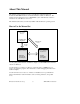
Hardware Configuration and Installation Chapter 2 Install the Hardware Perform the following steps to install the STD-GPIB. 1. Power off your STD/STD32 system. Keep the system plugged in so that it remains grounded while you install the STD-GPIB. 2. Remove any front plates that are blocking the access to the backplane slot. 3. Insert the STD-GPIB into any unused slot with the GPIB connector facing away from the backplane, as shown in Figure 2-1.
Chapter 2 Note: Hardware Configuration and Installation If you plan to perform HS488 high-speed protocol transfers, you must configure the NI-488.2 software for the amount of GPIB cable length in your system. The 5 in. GPIB ribbon cable must be added to your total GPIB cable length. 5. Mount the feedthrough panel assembly onto the STD/STD32 card cage using the two large thumbscrews. 6. Check that the installation resembles Figure 2-2.
Hardware Configuration and Installation Chapter 2 Configure the Hardware Follow the instructions in this section to change the hardware settings of the STD-GPIB before you install it.
Chapter 2 Hardware Configuration and Installation Figure 2-3 shows the location of the configuration jumpers and switches on the STD-GPIB. 1 2 8 1 2 Interrupt Level DMA Channel 3 4 3 4 5 7 Assembly Number 5 Serial Number 6 Product Name Shield Ground 6 7 8 Mode of Operation Base I/O Address Figure 2-3. STD-GPIB Parts Locator Diagram © National Instruments Corp.
Hardware Configuration and Installation Chapter 2 Selecting the Base I/O Address STD/STD32 computers have a segment of address space reserved for input and output. This segment is referred to as the I/O address space. The base I/O address of an STD/STD32 module such as the STD-GPIB is the first position in the I/O address space occupied by the STD/STD32 module. By default, the STD-GPIB is configured to use base I/O address 2C0 hex.
Chapter 2 Hardware Configuration and Installation Table 2-2.
Hardware Configuration and Installation Chapter 2 Push this side down (ON) for logic 0 Push this side down (OFF) for logic 1 1 0 OFF 1 2 3 4 5 Binary 9 8 7 6 5 Switch Set to Base I/O Address hex 300 0 Hex 1 1 3 0 0 0 0 0 0 0 0 0 0 1 OFF 1 2 3 4 5 Binary 9 8 7 6 5 Switch Set to Default Base I/O Address hex 2C0 Hex 1 0 2 1 1 0 0 C 0 0 0 0 0 Figure 2-4. Base I/O Address Switch Settings 4.
Chapter 2 Hardware Configuration and Installation Selecting the Interrupt Request Line STD/STD32 computers have a series of interrupt lines available to devices. Some of the interrupt lines reside in the backplane, and the others are available through a 10-pin frontplane connector. Devices use interrupts to get immediate service from the CPU for asynchronous events. Your GPIB hardware and the NI-488.2 software use interrupts to get service from the CPU when necessary.
Hardware Configuration and Installation Chapter 2 Ziatech W2 Figure 2-5 shows the setting for IRQ11 in a Ziatech AT-compatible computer. WinSystems IRQ 5 IRQ 5 IRQ 6 IRQ 9 IRQ 9 IRQ 7 IRQ 14 IRQ 10 IRQ 10 IRQ 11 IRQ 11 IRQ 12 IRQ 14 IRQ 12 W1 IRQ 15 Figure 2-5. Interrupt Jumper Setting for IRQ11 in a Ziatech Computer STD-GPIB for Windows 2-10 © National Instruments Corp.
Chapter 2 Hardware Configuration and Installation Ziatech W2 Figure 2-6 shows the setting for IRQ5 in a WinSystems AT-compatible computer. WinSystems IRQ 5 IRQ 5 IRQ 6 IRQ 9 IRQ 9 IRQ 7 IRQ 14 IRQ 10 IRQ 10 IRQ 11 IRQ 11 IRQ 12 IRQ 14 IRQ 12 W1 IRQ 15 Figure 2-6. Interrupt Jumper Setting for IRQ5 in a WinSystems Computer If you do not want to use interrupts, you can disable interrupt levels on the STD-GPIB by leaving the jumper as shown in Figure 2-7. © National Instruments Corp.
Ziatech Chapter 2 W2 Hardware Configuration and Installation WinSystems IRQ 5 IRQ 5 IRQ 6 IRQ 9 IRQ 9 IRQ 7 IRQ 14 IRQ 10 IRQ 10 IRQ 11 IRQ 11 IRQ 12 IRQ 14 IRQ 12 W1 IRQ 15 Figure 2-7. Jumper Setting for Disabling Interrupts 4. Record your new setting on the STD-GPIB Hardware and Software Configuration Form in Appendix C, Customer Communication. 5. Remember that after you install the NI-488.
Chapter 2 1. Hardware Configuration and Installation Choose a new DMA channel setting. You can use channel 5 or 6. If you are installing more than one STD-GPIB, each module must either use a unique DMA channel or must not use DMA at all. 2. Locate the jumpers at W3 that select the DMA channel. Refer to the parts locator diagram, Figure 2-3. 3. Change the jumper settings to configure the STD-GPIB to the new DMA channel.
Hardware Configuration and Installation Chapter 2 Using Programmed I/O for GPIB Transfers W3 As an alternative to DMA transfers, you can use programmed I/O. To use programmed I/O, you should disable DMA for the STD-GPIB by moving the jumpers as shown in Figure 2-9. DRQ 6 DACK 6 DRQ 5 DACK 5 Figure 2-9.
Chapter 2 Hardware Configuration and Installation W4 Logic Ground Connected to Shield Ground (Default) W4 Logic Ground Disconnected from Shield Ground Figure 2-10. Ground Configuration Jumper Settings 3. Record the jumper setting on the STD-GPIB Hardware and Software Configuration Form in Appendix C, Customer Communication. Setting the Operating Mode The STD-GPIB can operate in 8-bit or 16-bit mode. By default, the STD-GPIB is configured to operate in 16-bit mode.
Hardware Configuration and Installation 3. Chapter 2 Record the jumper setting on the STD-GPIB Hardware and Software Configuration Form in Appendix C, Customer Communication. Now that you have properly configured the hardware, return to the Install the Hardware section at the beginning of this chapter for the installation instructions. STD-GPIB for Windows 2-16 © National Instruments Corp.
Chapter 3 Software Installation and Configuration This chapter contains instructions to help you install and configure your NI-488.2 software. NI-488.2 Software Components The STD-GPIB is functionally equivalent to the AT-GPIB/TNT and is packaged with the NI-488.2 software for the AT-GPIB/TNT.
Software Installation and Configuration Chapter 3 The software installation begins with the following screen: The interactive Windows setup program takes you through the necessary steps to install the NI-488.2 software. For help during the installation, press the Help button. You can exit the setup at any time by pressing the Exit button. 3. After the installation is complete, restart your system. After you have installed your software, you might want to view or modify the driver configuration.
Chapter 3 Software Installation and Configuration To run the GPIB software configuration utility, double-click on the GPIB icon in the Control Panel , which is located in the Main group of the Program Manager . The utility displays a list of all the GPIB modules and device names. Double-click on any name to examine or edit it. The correct board type to use for the STD-GPIB in the configuration utility is AT-GPIB/TNT. You can use the online help if you have any questions.
Chapter 4 Installation Verification and Troubleshooting This chapter describes how to verify the hardware and software installation and how to troubleshoot problems. Troubleshooting ni-pnp Error Messages The ni-pnp.exe program should be located in the root directory of your boot drive, usually C:\. It should be run from your autoexec.bat file, so that ni-pnp executes every time your system is started.
Installation Verification and Troubleshooting Chapter 4 ni-pnp excludes that I/O port from future testing. If you know that you do not have any National Instruments Plug and Play modules in your system, you can configure ni-pnp so that it does not attempt to detect any Plug and Play modules. ni-pnp prompts you to choose between entering the fail-safe mode or disabling the detection of Plug and Play modules.
Chapter 4 Installation Verification and Troubleshooting Correcting Hardware Settings Follow these steps to troubleshoot Hardware Diagnostic Test error messages. 1. Make sure you are using a valid base I/O address. Run the Hardware Diagnostic Test again. When it prompts you for values, enter your base I/O address, but enter for both the interrupt request line and the DMA channel. If the test fails again, one of the following situations is occurring: 2.
Installation Verification and Troubleshooting 3. Chapter 4 Make sure you are using a valid DMA channel. Run the Hardware Diagnostic Test again. When it prompts you for values, enter the valid base I/O address and interrupt request line as determined in Steps 1 and 2, and enter the current DMA channel. If the test fails again, one of the following situations is occurring: • The DMA channel that you entered when prompted does not match the jumper setting of the STD-GPIB. Check the jumper setting again.
Chapter 4 Installation Verification and Troubleshooting Presence Test of Software Components The Software Diagnostic Test checks for the presence of ni-pnp.ini, gpib.ini and gpib.dll. If the ni-pnp.ini file is not found in the root of the boot drive, the following error message is displayed: An unexpected ERROR occurred: Unable to locate NI-PNP.INI Try reinstalling the NI-488.2 software. If the gpib.
Installation Verification and Troubleshooting Chapter 4 If this message appears, you could have one of the following situations: • The module might not be properly configured. Run the GPIB software configuration utility to verify the hardware settings. Refer to the Configure the Hardware section of Chapter 2, Hardware Configuration and Installation, for more information. • The module might not be properly installed.
Chapter 4 Installation Verification and Troubleshooting What should I do if one of the diagnostic tests fails with an error? Refer to the troubleshooting sections of this chapter for specific information about what might cause these tests to fail. When should I use the Win16 Interactive Control utility? You can use the Win16 Interactive Control utility to test and verify instrument communication, troubleshoot problems, and develop your application program.
Chapter 5 Using Your NI-488.2 Software This chapter introduces the Win16 Interactive Control utility and lists some programming considerations. Introduction to the Win16 Interactive Control Utility You can use the interactive control utility to enter NI-488 functions and NI-488.2 routines interactively and see the values returned by the function calls. Without writing an application, you can use the utility to do the following: • Verify GPIB communication with your device quickly and easily.
Appendix A Hardware Specifications This appendix describes the characteristics of the STD-GPIB and the recommended operating conditions. Table A-1. Electrical Characteristics Characteristic Maximum GPIB Transfer Rate 3-Wire (IEEE 488) High Speed (HS488) Power Requirement (from STD I/O channel) Specification Over 1 Mbyte/s* Over 1 Mbyte/s* +5 VDC 175 mA Typical 275 mA Maximum * Actual speed may vary considerably from speed shown because of system and instrumentation capabilities. Table A-2.
Appendix B Interrupt Routing This appendix contains useful information for you if you want to configure the interrupt lines for an STD/STD32 computer not manufactured by WinSystems or Ziatech, or a computer that is not AT-compatible. The STD-GPIB can assert interrupts using one of 10 interrupt lines. These interrupt sources are available on either the frontplane or backplane, as described in the following sections.
Interrupt Routing Appendix B Backplane Interrupts The five STD bus interrupts are INTRQ* (P44), INTRQ1* (P37), INTRQ2* (P50), INTRQ3* (E67), and INTRQ4* (P6). All five interrupts are supported in an STD32 backplane and all but INTRQ3* are supported in an STD-80 backplane. These interrupts are all active-low signals. Setting Interrupts on the STD-GPIB The interrupt routing for the STD-GPIB is shown in Table B-2. Table B-2.
Appendix C Customer Communication For your convenience, this section contains forms to help you gather the information necessary to help us solve technical problems you might have as well as a form you can use to comment on the product documentation. Filling out a copy of the Technical Support Form before contacting National Instruments helps us help you better and faster. National Instruments provides comprehensive technical assistance around the world. In the U.S.
Technical Support Form Photocopy this form and update it each time you make changes to your software or hardware, and use the completed copy of this form as a reference for your current configuration. Completing this form accurately before contacting National Instruments for technical support helps our applications engineers answer your questions more efficiently.
The problem is List any error messages The following steps will reproduce the problem
STD-GPIB Hardware and Software Configuration Form Record the settings and revisions of your hardware and software on the line to the right of each item. Update this form each time you revise your software or hardware configuration, and use this form as a reference for your current configuration. National Instruments Products • STD-GPIB Model (16-bit or 8-bit) • STD-GPIB Revision • NI-488.
• Application Programming Language (Microsoft C, Visual Basic for Windows) • Other Modules in System • Base I/O Addresses of Other Modules • Interrupt Levels of Other Modules • DMA Channels of Other Modules
Documentation Comment Form National Instruments encourages you to comment on the documentation supplied with our products. This information helps us provide quality products to meet your needs. Title: Getting Started with Your STD-GPIB and the NI-488.2™ Software for Windows Edition Date: December 1995 Part Number: 321042A-01 Please comment on the completeness, clarity, and organization of the manual.
If you find errors in the manual, please record the page numbers and describe the errors. Thank you for your help.
Glossary Prefix Meaning Value millicentikilomega- 10-3 10-2 103 106 mckM- ° % degrees percent A ANSI ASIC C CPU DMA EISA FCC GPIB hex Hz IEEE in.