Quick Start Guide FieldPoint™ cFP-21xx What You Need to Get Set Up • • • • cFP-21xx LabVIEW RT controller Mounting hardware (DIN rail, panel-mount, or rack-mount accessory) I/O module(s) cFP-BP-x backplane, connector blocks, cables • • • • • 11–30 VDC power supply Accessories: Ethernet cable, number 2 Phillips screwdriver PC running Windows FieldPoint software 4.1.
1. Mount the Compact FieldPoint Backplane You can mount the cFP-BP-x backplane on a 35mm DIN rail, on a panel, or in a standard 19 in. rack. Before using any of these mounting methods, record the serial number from the back of the backplane. Each set of mounting instructions in this document includes an instruction to connect the protective earth (PE) ground terminal on the cFP-BP-x backplane to the system safety ground. The backplane PE ground terminal has the following symbol stamped beside it: .
127 mm (5.00 in.) Min. 165 mm (6.50 in.) Cabling Clearance 106 mm (4.18 in.) Min. 182 mm (7.18 in.) 4 slots = 246 mm (9.68 in.) 8 slots = 441 mm (17.4 in.) Cabling Clearance Cooling Outline 51 mm (2 in.) All Around 4 slots = 246 mm (9.68 in.) 8 slots = 441 mm (17.4 in.) Cooling Outline 51 mm (2 in.) Cooling Outline 51 mm (2 in.) If you are using UL Recognized I\O modules with the Compact FieldPoint system, you must install the entire system in a suitably rated, UL Listed NEMA or IP enclosure.
NI recommends that you use one of the mounting systems described in this document. If you decide to use a custom mounting solution, make sure that the screws you use are short enough to fit in the holes in the backplane. The screw holes are 5 mm (0.2 in.) deep. Caution cFP-21xx Quick Start Guide 4 ni.
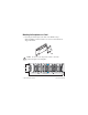
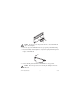
Mounting the Backplane on a Panel 1. Fasten the panel-mount plates to the back of the cFP-BP-x using a number 2 Phillips screwdriver and the 8-32 × 5/16 in. countersink screws shipped with the kit. L NA NTS TIO ME NA RU INST Do not use screws longer than 5/16 in. to fasten the panel-mount plates to the backplane. Caution 102 mm (4 in.) 457 mm (18 in.
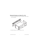
104.78 mm (4.1 in.) 127.00 mm 63.50 mm (2.5 in.) (5.0 in.) 407.80 mm (16.1 in.) 387.60 mm (15.3 in.) 311.40 mm (12.3 in.) 129.54 mm (5.1 in.) 33.15 mm (1.3 in.) 22.23 mm (0.9 in.) 440.94 mm (17.4 in.) 102 mm (4 in.) 260 mm (10.25 in.) cFP-21xx Quick Start Guide 6 ni.
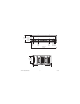
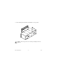
104.74 mm (4.1 in.) 127.00 mm 63.46 mm (2.5 in.) (5.0 in.) 211.84 mm (8.3 in.) 161.04 mm (6.3 in.) 84.84 mm (3.3 in.) 34.04 mm (1.3 in.) 22.19 mm (0.9 in.) 245.87 mm (9.6 in.) 2. Bolt or screw the panel-mount accessory to a panel. 3. Connect the PE ground terminal on the cFP-BP-x to safety ground. Caution Disconnect power before removing the backplane from the panel. Mounting the Backplane on a DIN Rail NI recommends DIN rail mounting for the cFP-BP-4 only.
L NA TS TIO EN NATRUM INS Do not use screws longer than 5/16 in. to fasten the DIN rail clip to the backplane. Caution 2. Insert one edge of the DIN rail into the deeper opening of the DIN rail clip. 3. Press down firmly on the backplane to compress the spring until the clip locks in place on the DIN rail. 4. Connect the PE ground terminal on the cFP-BP-4 to safety ground. Disconnect power before removing the backplane from the DIN rail. Caution cFP-21xx Quick Start Guide 8 ni.
Mounting the Backplane in a Standard 19 in. Rack 1. Fasten the rack-mount bracket to the back of the cFP-BP-x using the captive screws on the bracket. L NA TS TIO EN NATRUM INS 2. Bolt the rack-mount accessory to a standard 19 in. rack.
3. Connect the PE ground terminal on the cFP-BP-x to safety ground. L NA TS TIO EN NATRUM INS Disconnect power before removing the backplane from the DIN rail. Caution cFP-21xx Quick Start Guide 10 ni.
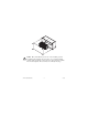
2. Install the cFP-21xx Controller on the Backplane 1. Make sure that no power is connected to the controller. 2. Make sure that the cFP-21xx controller is right side up with the NI logo at the top, and align the captive screws on the controller with the holes on the backplane. 3. Seat the card edge at the back of the controller in the card-edge connector on the backplane. 4. Press the controller firmly to seat it on the backplane. 5. Using a number 2 Phillips screwdriver with a shank of at least 64 mm (2.
3. Install I/O Modules on the Backplane 1. Align the captive screws on the I/O module with the holes on the backplane. 2. Press firmly to seat the I/O module on the backplane. 3. Using a number 2 Phillips screwdriver with a shank of at least 64 mm (2.5 in.) length, tighten the captive screws to 1.1 N · m (10 lb · in.) of torque. 4. Repeat this procedure to install additional I/O modules on the backplane. cFP-21xx Quick Start Guide 12 ni.
4. Install Connector Blocks on the Backplane In order to connect I/O modules to input signals or to external loads, you need to install a cFP-CB-x connector block or other connectivity accessory for each I/O module on the backplane. Use the connector socket to the right of each I/O module socket. Do not insert or remove connector blocks or other connectivity accessories while power is applied to them. Caution 1. Wire field devices as described in the I/O module and connector block operating instructions.
5. Connect the cFP-21xx to Your Network Connect the cFP-21xx controller to an Ethernet network using the RJ-45 Ethernet port on the controller. Use a standard Category 5 Ethernet cable to connect the cFP-21xx to an Ethernet hub, or use an Ethernet crossover cable to connect the controller directly to a computer. To prevent data loss and to maintain the integrity of your Ethernet installation, do not use a cable longer than 100 m.
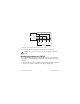
6. Wire Power to the Compact FieldPoint System Each cFP-21xx on your network requires an 11–30 VDC power supply. 1. Connect the positive lead of the primary power supply to one of the V1 terminals and the negative lead to one of the C terminals. 2. If you are using a backup power supply, connect the positive lead to V2 and the negative lead to one of the C terminals. The cFP-21xx uses the power supply with the higher voltage level. V2 is isolated from the other V terminals.
7. Power Up the cFP-21xx Check the DIP switches on the controller, making sure that the RESET IP switch is in the OFF position. Plug in each power supply to the Compact FieldPoint system. The cFP-21xx runs a power-on self test (POST) that takes several seconds. You should see the POWER and STATUS LEDs come on. After about three seconds, the STATUS LED begins flashing steadily. The cFP-21xx is ready to be configured. If you have already assigned an IP address to the cFP-21xx, the STATUS LED turns off.
8. Install Software on the Host PC 1. Install the software packages you plan to use, such as LabVIEW, the LabVIEW Real-Time Module, Measurement Studio, VI Logger, or LabWindows™/CVI™, before you install the FieldPoint software. The FieldPoint software installation installs the LabVIEW VIs and examples and the LabWindows/CVI instrument driver only if it finds the corresponding development software installed. 2. Close all other applications. 3.
Compact FieldPoint Safety Information The following section contains important safety information that you must follow when installing and using Compact FieldPoint products. Do not operate Compact FieldPoint products in a manner not specified in the user manual or operating instructions. Misuse of the product can result in a hazard. You can compromise the safety protection built into the product if the product is damaged in any way. If the product is damaged, return it to National Instruments for repair.
Operate the product only at or below Pollution Degree 2. Pollution is foreign matter in a solid, liquid, or gaseous state that can reduce dielectric strength or surface resistivity. The following is a description of pollution degrees: • Pollution Degree 1 means no pollution or only dry, nonconductive pollution occurs. The pollution has no influence. • Pollution Degree 2 means that only nonconductive pollution occurs in most cases.
impulse withstand voltage levels that commonly occur in electrical distribution systems. The following is a description of measurement categories: • Measurement Category I is for measurements performed on circuits not directly connected to the electrical distribution system referred to as MAINS1 voltage. This category is for measurements of voltages from specially protected secondary circuits.
Using This Product Safely in Hazardous Locations This product is suitable for use in U.S. and Canada: Class I, Division 2, Groups A, B, C, D, T4 hazardous locations; and nonhazardous locations. Caution Explosion hazard—Substitution of components may impair suitability for Class I, Division 2. Explosion hazard—Do not disconnect equipment unless power has been switched off or the area is known to be nonhazardous. Equipment must be used within its electrical and environmental ratings.
Memory cFP-2100........................................... 64 MB nonvolatile; 64 MB DRAM cFP-2110........................................... 64 MB nonvolatile; 128 MB DRAM cFP-2120........................................... 128 MB nonvolatile; 128 MB DRAM Memory lifetime (nonvolatile).......... 300,000 writes per sector For information about the memory used by the LabVIEW Real-Time Module and the operating system, go to ni.com/info and enter rdfpec. Serial Ports cFP-2100....................................
RS-485 (DTE) serial port Baud rate .................................... 110 to 115,200 bps Data bits...................................... 5, 6, 7, 8 Stop bits...................................... 1, 1.5, 2 Parity .......................................... Odd, Even, Mark, Space Flow control ............................... XON/XOFF Wire mode .................................. 4-wire Isolation voltage, port to earth ground Continuous ........................... 100 Vrms Dielectric withstand .............
Environmental FieldPoint modules are intended for indoor use only. For outdoor use, they must be installed in a suitable sealed enclosure. Operating temperature ...................... –40 to 70 °C Storage temperature .......................... –40 to 85 °C Humidity ........................................... 10 to 90% RH, noncondensing Maximum altitude............................. 2,000 m; at higher altitudes the isolation voltage ratings must be lowered Pollution Degree ...............................
Note For UL, hazardous location, and other safety certifications, refer to the product label or visit ni.com/certification, search by model number or product line, and click the appropriate link in the Certification column.
Refer to the Declaration of Conformity (DoC) for this product for any additional regulatory compliance information. To obtain the DoC for this product, visit ni.com/certification, search by model number or product line, and click the appropriate link in the Certification column. Note Cabling The table below shows the standard Ethernet cable wiring connections for both normal and crossover cables.
Where to Go for Support The National Instruments Web site is your complete resource for technical support. At ni.com/support you have access to everything from troubleshooting and application development self-help resources to email and phone assistance from NI Application Engineers. National Instruments corporate headquarters is located at 11500 North Mopac Expressway, Austin, Texas, 78759-3504. National Instruments also has offices located around the world to help address your support needs.
National Instruments, NI, ni.com, and LabVIEW are trademarks of National Instruments Corporation. Refer to the Terms of Use section on ni.com/legal for more information about National Instruments trademarks. Other product and company names mentioned herein are trademarks or trade names of their respective companies. For patents covering National Instruments products/technology, refer to the appropriate location: Help»Patents in your software, the patents.