
Network Card User Manual


FP-CTR-502 and cFP-CTR-502 16 ni.com
Status Indicators
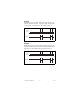
Figure 12 shows the status indicator LEDs on the [c]FP-CTR-502.
Figure 12. Status Indicators
The [c]FP-CTR-502 has two green status LEDs, POWER and
READY. After you install the [c]FP-CTR-502 onto a terminal base
or backplane and apply power to the connected network module,
the green POWER indicator lights and the [c]FP-CTR-502
informs the network module of its presence. When the network
module recognizes the [c]FP-CTR-502, it sends initial
configuration information to the [c]FP-CTR-502. After the
[c]FP-CTR-502 receives this initial information, the green
READY indicator lights and the module is in normal operating
mode.
In addition to the green POWER and READY indicators, each
channel has a numbered, green status indicator that lights when the
channel is in the ON state.
Upgrading the FieldPoint Firmware
You may need to upgrade the FieldPoint firmware when you add
new I/O modules to the FieldPoint system. For more information
on determining which firmware you need and how to upgrade the
firmware, go to
ni.com/info and enter fpmatrix.
Isolation and Safety Guidelines
Caution Read the following information before
attempting to connect the [c]FP-CTR-502 to any circuits
that may contain hazardous voltages.
This section describes the isolation of the [c]FP-CTR-502 and its
compliance with international safety standards. The field wiring
connections are isolated from the backplane and the inter-module
communication bus. The isolation is provided by the module,
which has optical and galvanic isolation barriers designed and
tested to protect against transient fault voltages of up to 2,300 V
rms
.