FieldPoint Operating Instructions FP-CTR-502 and cFP-CTR-502 Eight-Channel, 16-Bit Counter Module These operating instructions describe how to install and use the National Instruments FP-CTR-502 and cFP-CTR-502 counter modules (referred to inclusively as the [c]FP-CTR-502). For information about configuring and accessing the [c]FP-CTR-502 over a network, refer to the user manual for the FieldPoint network module you are using.
Installing the FP-CTR-502 The FP-CTR-502 mounts on a FieldPoint terminal base (FP-TB-x), which provides operating power to the module. Installing the FP-CTR-502 onto a powered terminal base does not disrupt the operation of the FieldPoint bank. To install the FP-CTR-502, refer to Figure 1 and complete the following steps: 1. Slide the terminal base key to either position X, used for any module, or position 8, used for the FP-CTR-502 module. 2.
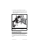
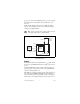
2. Press firmly to seat the cFP-CTR-502 on the backplane. 3. Using a number 2 Phillips screwdriver with a shank of at least 64 mm (2.5 in.) length, tighten the captive screws to 1.1 N ⋅ m (10 lb ⋅ in.) of torque. The nylon coating on the screws prevents them from loosening. 4 3 5 2 4 2 1 1 cFP I/O Module 2 Captive Screws 3 cFP Controller 4 Screw Holes 5 cFP Backplane Figure 2.
Use a 5–30 VDC external power supply for the input channels. The power supply must provide enough current to power all of the input channels and all of the field devices on the output channels. Connect the external power supply to multiple V and VSUP terminals and to multiple C and COM terminals as needed to ensure that the maximum current through any terminal is 2 A or less. Install a 2 A maximum, fast-acting fuse between the external power supply and the V or VSUP terminal on each channel.
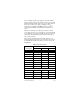
Table 1. Terminal Assignments (Continued) Terminal Numbers Channel Name VIN or VOUT1 VSUP2 COM Outputs 1 2 Output 0 13 29 30 Output 1 14 29 30 Output 2 15 31 32 Output 3 16 31 32 Install a 1 A maximum, fast-acting fuse on each VOUT terminal. Install a 2 A maximum, fast-acting fuse on each V and VSUP terminal. Inputs Each input channel has one input terminal, VIN .
VIN is 21 V or lower, and an OFF state when VIN is 22 V or higher. The channel state is indeterminate when VIN is between 21 V and 22 V. Ensure that the sinking-output devices have OFF state leakage currents of less than 0.3 mA so they do not send false ON state readings to the [c]FP-CTR-502. You must use the same ground for all of the input and output channels on the [c]FP-CTR-502.
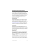
+ – 2 A max V 5–30 VDC External Power Supply C VSUP SinkingOutput Circuitry Load VOUT 1 A max COM To next channel [c]FP-CTR-502 Figure 4. Wiring an Output Channel to a Sourcing-Input Device If you connect a [c]FP-CTR-502 output to an externally powered sourcing-input device, be aware that the voltage applied to the VOUT terminal by the external device must not exceed the voltage level of the power supply connected to the [c]FP-CTR-502.
Configuring Count-Input Channels Channels 0–7 are count-input channels. In FieldPoint software, you can configure each count-input channel to operate with attributes and commands. In the Channel Configuration dialog box, select attributes for each channel from the Attributes menu and commands from the Commands menu. The following sections describe the different attributes and commands you can select when you are configuring the count-input channels.
to Channel 0, Channel 0 to Channel 7, Channel 7 to Channel 6, and so on. If you select this option for all of the channels, no counting occurs. Gate Source Select Gate Input 0–3 from the Value menu to associate a gate-input channel with a count-input channel. If the count-input channel uses one of the external gate inputs, counting is enabled when the gate-input signal is high and is disabled when the signal is low, as shown in Figure 6. The gate-input signal is high when the channel is ON.
Noise Rejection Each count-input channel has a software-enabled lowpass filter that you can set to reject frequencies above 200 Hz or 50 kHz. Select 200 Hz or 50 kHz from the Value menu to configure noise rejection. The default is 50 kHz. Control You can set the Control command to increment or reset by selecting Increment or Reset from the Action menu. The increment-control command increases the count-input channel in value by one. The reset-control command resets the count-input channel.
Output Mode For each output channel select one of the following output modes from the Value menu: Toggle, Reset Off; Toggle, Reset On; On Pulse; or Off Pulse. The output modes work only if you select Counter Channel 0–7 for the Output Source. The following sections describe the different output modes. Toggle, Reset Off In Toggle, Reset Off mode, the output channel starts low and goes high when the terminal count is exceeded.
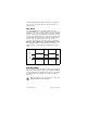
On Pulse In On Pulse mode, the output channel starts low and goes high when the terminal count is exceeded. The output channel returns to low after one count. In Figure 9, the terminal count is 4. Count Input 0 1 2 3 4 0 1 2 3 4 0 1 Output Figure 9. Output of a Channel Set to On Pulse Mode Off Pulse In Off Pulse mode, the output channel starts high and goes low when the terminal count is exceeded. The output channel returns to high after one count. In Figure 10, the terminal count is 4.
Application Note: Generating a Continuous Pulse Train You can use two [c]FP-CTR-502 count-input channels and one output channel to generate a continuous pulse train with a controllable duty cycle and period. The first count-input channel serves as a clock prescaler and divides the input clock by a fixed value. This generates a slower clock for the second count-input channel, which serves as the pulse counter. The pulse counter is the output source for the output channel.
4. Set the Count Source of the prescaler counter to the clock on which you want to base your pulse train. This can be the external counter input or one of the [c]FP-CTR-502 internal references. 5. Subtract 1 from the value that you want to divide the input clock by, and set the terminal count of the prescaler counter to the result. For example, a terminal count of 4 divides the input clock by 5.
To determine the frequency of the output from the pulse counter, use the following formula: f pre f pulse = -------------------------------term pulse + 1 where fpulse is the pulse counter output frequency fpre is the prescaler counter output frequency termpulse is the terminal count value for the pulse counter Step 3. Configure the Pulse Train Output Channel To configure the pulse train output channel, complete the following steps: 1.
Status Indicators Figure 12 shows the status indicator LEDs on the [c]FP-CTR-502. Figure 12. Status Indicators The [c]FP-CTR-502 has two green status LEDs, POWER and READY. After you install the [c]FP-CTR-502 onto a terminal base or backplane and apply power to the connected network module, the green POWER indicator lights and the [c]FP-CTR-502 informs the network module of its presence. When the network module recognizes the [c]FP-CTR-502, it sends initial configuration information to the [c]FP-CTR-502.
Follow these guidelines to ensure a safe total system. • The [c]FP-CTR-502 has a safety isolation barrier between the I/O channels and the inter-module communication bus. There is no isolation between channels unless otherwise noted. If any of the channels on a module are wired at a hazardous potential, make sure that all other devices or circuits connected to that module are properly insulated from human contact.
Specifications The following specifications are typical for a range of –40 to 70 °C unless otherwise noted.1 Input Characteristics Number of channels.......................... 12 (8 count, 4 gate) Input type .......................................... 5–30 VDC sourcing, compatible with TTL devices and other 5, 12, or 24 VDC devices Maximum input voltage.................... 30 VDC Input threshold level (VSUP is the external supply voltage) Typical ........................................ VSUP – 2.
Maximum output current Per channel ................................. 1 A Across all channels..................... 4 A Output impedance............................. 0.12 Ω Output bandwidth ............................. 16 kHz for a current flow ≥3.2 mA Maximum off-state leakage current.................................. 50 µA Physical Characteristics Indicators .......................................... Green POWER and READY indicators, 16 green input/output state indicators Weight FP-CTR-502 ...............
Shock and Vibration These specifications apply only to the cFP-CTR-502. NI recommends Compact FieldPoint if your application is subject to shock and vibration. Operating vibration, random (IEC 60068-2-64).............................. 10–500 Hz, 5 grms Operating vibration, sinusoidal (IEC 60068-2-6)................................ 10–500 Hz, 5 g Operating shock (IEC 60068-2-27)..............................
CE Compliance This product meets the essential requirements of applicable European Directives, as amended for CE Marking, as follows: Low-Voltage Directive (safety)......... 73/23/EEC Electromagnetic Compatibility Directive (EMC) ............................... 89/336/EEC Note Refer to the Declaration of Conformity (DoC) for this product for any additional regulatory compliance information. To obtain the DoC for this product, click Declarations of Conformity Information at ni.com/hardref.nsf/.
Where to Go for Support For more information about setting up the FieldPoint system, refer to these National Instruments documents: • FieldPoint network module user manual • Other FieldPoint I/O module operating instructions • FieldPoint terminal base and connector block operating instructions Go to ni.com/support for the most current manuals, examples, and troubleshooting information. For telephone support in the United States, create your service request at ni.