CALIBRATION PROCEDURE NI 4070/4072 6½-Digit FlexDMM ™ This document contains step-by-step instructions for writing an external calibration procedure for the National Instruments PXI/PCI-4070 and NI PXI-4072 digital multimeters (DMMs). Each of these National Instruments DMMs is a 6½-digit FlexDMM and 1.8 MS/s isolated digitizer. For more information on calibration, visit ni.com/ calibration. Contents Conventions ............................................................................................
Conventions The following conventions are used in this document: » The » symbol leads you through nested menu items and dialog box options to a final action. The sequence File»Page Setup»Options directs you to pull down the File menu, select the Page Setup item, and select Options from the last dialog box. ♦ The ♦ symbol indicates that the following text applies only to a specific product, a specific operating system, or a specific software version.
The procedures in this document are described using C function calls. You also can program in LabVIEW using the VIs that correspond to the C function calls. Documentation Requirements In addition to this calibration document, you may find the following references helpful in writing your calibration utility. All of these documents are installed on your computer when you install NI-DMM. To locate them, select Start»All Programs»National Instruments» NI-DMM»Documentation.
Calibration Interval The accuracy requirements of your measurement application determine how often you should calibrate the NI 4070/4072. NI recommends performing a complete calibration at least once every two years. NI does not guarantee the absolute accuracy of the NI 4070/4072 beyond this two-year calibration interval. You can shorten the calibration interval based on the demands of your application. Refer to Appendix A: Calibration Options for more information.
300 pF range, a capacitor with values between 90–100% of full scale should be used. NI suggests using the capacitance standards of the SCA Series from IET Labs. This calibration procedure assumes the use of 270 pF, 1 nF, 100 nF, 10 μF, and 1000 μF standards. • If you are using cables to connect the verification capacitors to the NI 4072 banana plug connectors, NI recommends using Pasternack PE3005 banana-to-banana coaxial cables with length ≤4 inches and total capacitance ≤40 pF.
• Clean any oxidation from the banana plugs on the Fluke 5440 cables before plugging them into the binding posts of the calibrator or the banana plug connectors of the NI 4070/4072. Oxidation tarnishes the copper banana plugs so that they appear dull rather than shiny and leads to greater thermal EMF. • Keep the blue banana plugs on the Fluke 5440 cables connected to the V GUARD binding post of the calibrator at all times.
Fluke 5700A/5720A user documentation for instructions on calibrating these devices. Ensure that both the calibrator and the NI 4070/4072 (installed in a powered-on PXI chassis or PC) are warmed up for at least 60 minutes before you begin this procedure. Note 3. Call niDMM_init with the resource name of the device to create a session. You use this session in all subsequent function calls throughout the verification procedures.
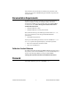
Verifying DC Voltage To verify DC voltage of the NI 4070/4072, complete the following steps: 1. Plug in the insulated banana plug shorting bar across the HI and LO banana plug connectors on the NI 4070/4072. 2. Wait one minute for the thermal EMF to stabilize. 3. Call niDMM_reset. 4. Call niDMM_ConfigureMeasurement with the following parameters: 5.
12. Set the input resistance of the NI 4070/4072 to 10 MΩ by calling niDMM_SetAttributeViReal64 with the following parameters: • Attribute_ID = NIDMM_ATTR_INPUT_RESISTANCE • Attribute_Value = NIDMM_VAL_10_MEGAOHM 13. Call niDMM_Read. Verify that this measurement falls between the limits listed in Table 15. 14. Call niDMM_ConfigureMeasurement with the following parameters: • Function = NIDMM_VAL_DC_VOLTS • Range = 100 • Resolution = 100e–6 15.
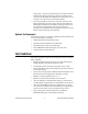
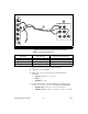
1 2 6½-Digit FlexDMM OUTPUT VΩA HI 300V MAX INPUT V 3 W SENSE VΩ HI HI LO LO LO 1A, 250V AMPS MAX HI 300V SENSE MAX W 4W HI AUX CURRENT LO GUARD GROUND AUX I/O 5V MAX CAT II 1 NI 4070/4072 2 Fluke 5700A/5720A Calibrator 3 Fluke 5440 Cable Figure 1. Cable Connections for Voltage and 2-Wire Resistance Table 1.
27. Call niDMM_ConfigureMultiPoint with the following parameters: • Trigger Count = 1 • Sample Count = 10 • Sample Trigger = NIDMM_VAL_IMMEDIATE • Sample Interval = –1 28. Call niDMM_ReadMultiPoint with the following parameters: • Maximum Time = NIDMM_VAL_TIME_LIMIT_AUTO • Array Size = 10 Average the results by summing the returned reading array of the function and dividing by the returned actual number of points. Store the result as the 100 mV >10 GΩ mode offset. 29.
34. Set the input resistance of the NI 4070/4072 to >10 GΩ by calling niDMM_SetAttributeViReal64 with the following parameters: • Attribute_ID = NIDMM_ATTR_INPUT_RESISTANCE • Attribute_Value = NIDMM_VAL_GREATER_THAN_10_GIGAOHM 35. Call niDMM_Read. Subtract the previously stored 100 mV >10 GΩ mode offset from this measurement, and verify that the result falls between the limits listed in Table 15. 36.
45. Set the input resistance of the NI 4070/4072 to >10 GΩ by calling niDMM_SetAttributeViReal64 with the following parameters: • Attribute_ID = NIDMM_ATTR_INPUT_RESISTANCE • Attribute_Value = NIDMM_VAL_GREATER_THAN_10_GIGAOHM 46. Call niDMM_Read. Verify that this measurement falls between the limits listed in Table 15. 47.
58. Set the input resistance of the NI 4070/4072 to 10 MΩ by calling niDMM_SetAttributeViReal64 with the following parameters: • Attribute_ID = NIDMM_ATTR_INPUT_RESISTANCE • Attribute_Value = NIDMM_VAL_10_MEGAOHM 59. Call niDMM_Read. Verify that this measurement falls between the limits listed in Table 15. 60. Output –10 V on the calibrator. 61.
71. Call niDMM_ConfigureMeasurement with the following parameters: • Function = NIDMM_VAL_DC_VOLTS • Range = 300 • Resolution = 300e–6 72. Call niDMM_Read. Before you apply the voltage, the DMM must be in the 300 V range. 73. Output 300 V on the calibrator. 74. Call niDMM_Read. Verify that this measurement falls between the limits listed in Table 15. 75. Output –300 V on the calibrator. 76. Call niDMM_Read. Verify that this measurement falls between the limits listed in Table 15. 77.
5. Call niDMM_ConfigureMeasurement with the following parameters: • Function = NIDMM_VAL_AC_VOLTS • Range = 0.05 • Resolution = 50e–9 6. Call niDMM_Read. Verify that this measurement falls between the limits listed in Table 16. 7. Call niDMM_ConfigureMeasurement with the following parameters: • Function = NIDMM_VAL_AC_VOLTS_DCCOUPLED • Range = 0.05 • Resolution = 50e–9 8. Call niDMM_Read. Verify that this measurement falls between the limits listed in Table 16. 9.
13. Repeat step 12 for each of the remaining iterations shown in Table 2. Table 2. niDMM_ConfigureMeasurement Parameters Calibrator Output niDMM_ConfigureMeasurement Parameters Iteration Amplitude Frequency 1 50 mV 50 Hz 50 mV 2 3 4 5 6 7 Function Range Resolution NIDMM_VAL_AC_VOLTS 0.05 50e–9 50 Hz NIDMM_VAL_AC_VOLTS_DCCOUPLED 0.05 50e–9 50 mV 1 kHz NIDMM_VAL_AC_VOLTS 0.05 50e–9 50 mV 1 kHz NIDMM_VAL_AC_VOLTS_DCCOUPLED 0.05 50e–9 50 mV 1 kHz NIDMM_VAL_AC_VOLTS 0.
c. Call niDMM_Read. Verify that this measurement falls between the limits listed in Table 16. d. Call niDMM_ConfigureMeasurement again, changing Mode to NIDMM_VAL_AC_VOLTS_DCCOUPLED. e. Call niDMM_Read. Verify that this measurement falls between the limits listed in Table 16. Table 3.
21. Refer to Table 4 for the appropriate calibrator outputs and parameter values as you complete the following steps: a. On the calibrator, output the value listed in the Calibrator Output column in Table 4 for the current iteration. b. Call niDMM_ConfigureMeasurement with Mode set to NIDMM_VAL_AC_VOLTS and the remaining parameters as shown in Table 4 for the current iteration. c. Call niDMM_Read. Verify that this measurement falls between the limits listed in Table 16. d.
23. Call niDMM_ConfigureMeasurement with the following parameters: • Function = NIDMM_VAL_AC_VOLTS_DCCOUPLED • Range = 50 • Resolution = 50e–6 24. Call niDMM_Read. Verify that this measurement falls between the limits listed in Table 16. 25. Refer to Table 5 for the appropriate calibrator outputs and parameter values as you complete the following steps: a. On the calibrator, output the value listed in the Calibrator Output column in Table 5 for the current iteration. b.
26. Call niDMM_ConfigureMeasurement with the following parameters: • Function = NIDMM_VAL_AC_VOLTS_DCCOUPLED • Range = 300 • Resolution = 300e–6 27. Call niDMM_Read. The DMM must be in the 300 V range before you apply the voltage. 28. Output 219 V at 30 Hz on the calibrator. 29. Call niDMM_Read. Verify that this measurement falls between the limits listed in Table 16. 30. Refer to Table 6 for the appropriate calibrator outputs and parameter values as you complete the following steps: a.
31. Reset the calibrator for safety reasons. You have completed verifying the AC voltage of the NI 4070/4072. Select one of the following options: • If you want to continue verifying other modes, go to the Verifying 4-Wire Resistance section. • If you do not want to verify other modes and you are performing a post-adjustment verification, go to the Completing the Adjustment Procedures section.
Table 7. Fluke 5440 Cable Connections Fluke 5440 Cable Identification First cable Second cable Banana Plug Connector (NI 4070/4072) Banana Plug Color (Fluke 5440 Cable) Binding Post (Fluke 5700A/5720A Calibrator) HI Red OUTPUT HI LO Black OUTPUT LO (No connection) Blue V GUARD HI SENSE Red SENSE HI LO SENSE Black SENSE LO (No connection) Blue V GUARD 3. Wait two minutes for the thermal EMF to stabilize if the Fluke 5440 cables were not previously connected in this configuration. 4.
6. Repeat step 5 for each of the remaining iterations listed in Table 8. Table 8. niDMM_ConfigureMeasurement Parameters Iteration Calibrator Output 1 10 MΩ 2 niDMM_ConfigureMeasurement Parameters Function Range Resolution OffsetCompOhms NIDMM_VAL_4_WIRE_RES 10e6 10 OFF 1 MΩ NIDMM_VAL_4_WIRE_RES 1e6 1 OFF 3 100 kΩ NIDMM_VAL_4_WIRE_RES 100e3 0.1 OFF 4 10 kΩ NIDMM_VAL_4_WIRE_RES 10e3 0.
4. Call niDMM_ConfigureMeasurement with the following parameters: • Function = NIDMM_VAL_2_WIRE_RES • Range = 10e3 • Resolution = 0.01 5. Call niDMM_ConfigureOffsetCompOhms with OffsetCompOhms set to NIDMM_VAL_OFFSET_COMP_OHMS_ON. 6. Call niDMM_Read. Verify that this measurement falls between the limits listed in Table 18. 7. Call niDMM_ConfigureMeasurement with the following parameters: • Function = NIDMM_VAL_2_WIRE_RES • Range = 1e3 • Resolution = 1e–3 8.
19. Call niDMM_ConfigureMeasurement with the following parameters: • Function = NIDMM_VAL_2_WIRE_RES • Range = 100e6 • Resolution = 100 20. Call niDMM_Read and store the result as the 100 MΩ range offset. 21. Call niDMM_ConfigureMeasurement with the following parameters: • Function = NIDMM_VAL_2_WIRE_RES • Range = 10e6 • Resolution = 10 22. Call niDMM_Read and store the result as the 10 MΩ range offset. 23.
28. Call niDMM_ConfigureMeasurement with the following parameters: • Function = NIDMM_VAL_2_WIRE_RES • Range = 10e3 • Resolution = 0.01 29. Call niDMM_ConfigureMultiPoint with the following parameters: • Trigger Count = 1 • Sample Count = 4 • Sample Trigger = NIDMM_VAL_IMMEDIATE • Sample Interval = –1 30.
35. Call niDMM_ConfigureMultiPoint with the following parameters: • Trigger Count = 1 • Sample Count = 10 • Sample Trigger = NIDMM_VAL_IMMEDIATE • Sample Interval = –1 36. Call niDMM_ReadMultiPoint with the following parameters: • Maximum Time = NIDMM_VAL_TIME_LIMIT_AUTO • Array Size = 10 Average the results by summing the returned reading array of the function and dividing by the returned actual number of points. Store the result as the 100 Ω range offset. 37.
45. Call niDMM_Read. Subtract the previously stored 1 MΩ range offset from this measurement. Verify that the result falls between the tolerances listed in Table 18. 46. Output 100 kΩ on the calibrator without external sense or 2-wire compensation. 47. Call niDMM_ConfigureMeasurement with the following parameters: • Function = NIDMM_VAL_2_WIRE_RES • Range = 100e3 • Resolution = 0.1 48. Call niDMM_Read. Subtract the previously stored 100 kΩ range offset from this measurement.
57. Call niDMM_Read. Subtract the previously calculated 100 Ω range offset from this measurement. Verify that the result falls between the tolerances listed in Table 18. You have completed verifying the 2-wire resistance of the NI 4070/4072. Select one of the following options: • If you want to continue verifying other modes, go to the Verifying DC Current section.
Table 9. Fluke 5440 Cable Connections Banana Plug Connector (NI 4070/4072) Banana Plug Color (Fluke 5440 Cable) Binding Post (Fluke 5700A/5720A Calibrator) HI SENSE Red OUTPUT HI LO Black OUTPUT LO (No connection) Blue V GUARD 3. Call niDMM_reset to reset the NI 4070/4072 to a known state. 4. Set the current output on the calibrator to NORM and output 0 A. 5. Call niDMM_ConfigureMeasurement with the following parameters: • Function = NIDMM_VAL_DC_CURRENT • Range = 0.
13. Output 20 mA on the calibrator. 14. Call niDMM_Read. Verify that this measurement falls between the limits listed in Table 19. 15. Output –20 mA on the calibrator. 16. Call niDMM_Read. Verify that this measurement falls between the limits listed in Table 19. 17. Output 200 mA on the calibrator. 18. Call niDMM_ConfigureMeasurement with the following parameters: • Function = NIDMM_VAL_DC_CURRENT • Range = 0.2 • Resolution = 200e–9 19. Call niDMM_Read.
Verifying AC Current To verify the AC current of the NI 4070/4072, complete the following steps: 1. Reset the calibrator. 2. Fasten the connectors on one end of the Fluke 5440 cable to the NI 4070/4072 HI SENSE and LO banana plug connectors, and fasten the connectors on the other end of the cable to the HI and LO calibrator binding posts. Figure 3 shows the correct connections. Table 9 lists the cable connections. 3. Call niDMM_reset to reset the NI 4070/4072 to a known state. 4.
14. Call niDMM_ConfigureMeasurement with the following parameters: • Function = NIDMM_VAL_AC_CURRENT • Range = 1 • Resolution = 1e–6 15. Call niDMM_Read. Verify that this measurement falls between the limits listed in Table 20. 16. Output 1 A at 1 kHz on the calibrator. 17. Call niDMM_Read. Verify that this measurement falls between the limits listed in Table 20. You have completed verifying the AC current of the NI 4070/4072.
To verify the frequency of the NI 4070/4072, complete the following steps: 1. Note Remove all connections from the NI 4070/4072. Polarity is not important in steps 2, 3, and 5. 2. Connect one end of the coaxial cable to the Pomona 4892 double banana plug. 3. Tighten the other end of the coaxial cable in the screw terminal channels 5 and 39 of the TB-2715 terminal block. 4. Connect the TB-2715 with the coaxial cable attached to the NI 6608. 5.
12. Call GPCTR_Change_Parameter with the following parameters: • deviceNumber = the device number of the NI 6608, assigned by MAX • gpctrNum = ND_COUNTER_0 • paramID = ND_COUNT_2 • paramValue = 10e6 13. Call GPCTR_Control with the following parameters: • deviceNumber = the device number of the NI 6608, assigned by MAX • gpctrNum = ND_COUNTER_0 • action = ND_PROGRAM 14. Call niDMM_Read. Verify that this measurement falls between the limits listed in Table 21. 15.
Verifying Capacitance and Inductance (NI 4072 Only) This verification procedure only applies to the NI 4072 and requires additional test equipment, as indicated in the Additional Requirements for the NI 4072 section. Note The NI 4072 inductance accuracy is theoretically verified if the capacitance accuracy meets the specifications. If you have access to precision inductors, you can verify the inductance measurements by comparing your results with the published accuracy specifications.
To verify the capacitance measurements of the NI 4072, complete the following steps: 1. Disconnect any fixtures or cables from the NI 4072. 2. Call niDMM_reset to reset the NI 4070/4072 to a known state. 3. Call niDMM_ConfigureMeasurement with the following parameters: 4.
11. Call niDMM_ConfigureMeasurement with the following parameters: • Function = NIDMM_VAL_CAPACITANCE • Range = 300e-12 • Resolution = 50e-15 12. Set the number of averages of the NI 4072 to 20 by calling niDMM_SetAttributeViInt32 with the following parameters: • Attribute_ID = NIDMM_ATTR_LC_NUMBER_MEAS_TO_AVERAGE • Attribute_Value = 20 13. Call niDMM_Read. Verify that this measurement falls between the tolerances listed in Table 22.
19. Set the number of averages of the NI 4072 to 20 by calling niDMM_SetAttributeViInt32 with the following parameters: • Attribute_ID = NIDMM_ATTR_LC_NUMBER_MEAS_TO_AVERAGE • Attribute_Value = 20 Note If you use capacitance verification values that differ from the values listed in Table 10, verify that each measurement falls between the tolerances listed in Table 22. The tolerances shown in Table 22 correspond to the NI 4072 accuracy specifications. 20. Call niDMM_Read.
Adjustment Procedures This section explains how to adjust the NI 4070/4072. You can choose to perform these adjustment procedures with or without performing the verification procedures first. The parameters Range, Resolution, Expected Measurement, and Frequency used in function calls in this section have floating point values. For example, if Range = 1, the floating point value is 1.0. Refer to the NI Digital Multimeters Help for more information about parameter values.
Adjusting DC Voltage and Resistance To adjust the DC voltage and resistance of the NI 4070/4072, complete the following steps: Note 1. Fasten the connectors on one end of the Fluke 5440 cable to the appropriate banana plug connectors on the NI 4070/4072, and fasten the connectors on the other end of the cable to the appropriate calibrator binding posts. Figure 1 shows the correct connections. Table 1 lists the cable connections. 2.
10. Call niDMM_CalAdjustGain with the following parameters: • Mode = NIDMM_VAL_DC_VOLTS • Range = 10 • Input Resistance = NIDMM_VAL_GREATER_THAN_10_GIGAOHM • Expected Measurement = 10 11. Output –10 V on the calibrator. 12. Call niDMM_CalAdjustGain with the following parameters: • Mode = NIDMM_VAL_DC_VOLTS • Range = 10 • Input Resistance = NIDMM_VAL_GREATER_THAN_10_GIGAOHM • Expected Measurement = –10 13.
23. Output 0 Ω from the calibrator without external sense or 2-wire compensation. 24. Call niDMM_CalAdjustGain with the following parameters: • Mode = NIDMM_VAL_2_WIRE_RES • Range = 10e6 • Input Resistance = NIDMM_VAL_RESISTANCE_NA • Expected Value = the display on the calibrator for 0 Ω 25. Call niDMM_CalAdjustOffset with the following parameters: • Mode = NIDMM_VAL_2_WIRE_RES • Range = 10e6 • Input Resistance = NIDMM_VAL_RESISTANCE_NA 26.
36. Call niDMM_CalAdjustGain with the following parameters: • Mode = NIDMM_VAL_2_WIRE_RES • Range = 100e6 • Input Resistance = NIDMM_VAL_RESISTANCE_NA • Expected Value = the display on the calibrator for 0 Ω 37. Call niDMM_CalAdjustOffset with the following parameters: • Mode = NIDMM_VAL_2_WIRE_RES • Range = 100e6 • Input Resistance = NIDMM_VAL_RESISTANCE_NA 38. Output 100 kΩ on the calibrator with external sense turned on but without 2-wire compensation. 39.
. Call niDMM_CalAdjustOffset with the following parameters: • Mode = NIDMM_VAL_4_WIRE_RES • Range = 10e3 • Input Resistance = NIDMM_VAL_RESISTANCE_NA 47. Call niDMM_CalAdjustMisc with Type set to NIDMM_EXTCAL_MISCAL_RREF. 48. Call niDMM_SelfCal to self-calibrate the NI 4070/4072. 49. Output 0 Ω on the calibrator with external sense turned on but with 2-wire compensation turned off. 50.
58. Call niDMM_CalAdjustOffset with the following parameters: • Mode = NIDMM_VAL_2_WIRE_RES • Range = 1e6 • Input Resistance = NIDMM_VAL_RESISTANCE_NA 59. Call niDMM_CalAdjustOffset with the following parameters: • Mode = NIDMM_VAL_2_WIRE_RES • Range = 100e3 • Input Resistance = NIDMM_VAL_RESISTANCE_NA 60. Call niDMM_CalAdjustOffset with the following parameters: • Mode = NIDMM_VAL_2_WIRE_RES • Range = 10e3 • Input Resistance = NIDMM_VAL_RESISTANCE_NA 61.
• If you are not performing additional adjustments, refer to one of the following sections: – Verification Procedures—to verify your new calibration coefficients before saving them to the EEPROM – Completing the Adjustment Procedures—if you do not want to verify the adjustments you have just made Adjusting AC Voltage (AC- and DC-Coupled) Modes If you do not use the AC voltage modes for any measurements, or the accuracy of these modes is irrelevant, you can skip this section in the calibration procedure
Table 11.
7. Note Refer to Table 13 for the appropriate calibrator outputs and parameter values as you complete the following steps: a. On the calibrator, output the value listed in the Calibrator Output column in Table 13 for the current iteration. b. Call niDMM_CalAdjustACFilter with Mode set to NIDMM_VAL_AC_VOLTS and the remaining parameters as shown in Table 13 for the current iteration. The Session parameter remains the same for all instances of this function. c. 8.
Table 13. niDMM_CalAdjustACFilter Parameters (Continued) Calibrator Output Iteration Amplitude Frequency (kHz) 10 500 mV 5 500 mV 11 12 13 14 15 16 17 18 19 20 21 22 23 niDMM_CalAdjustACFilter Parameters Range (V) Frequency (Hz) NIDMM_VAL_AC_VOLTS 0.5 5e3 5 NIDMM_VAL_AC_VOLTS_DCCOUPLED 0.5 5e3 500 mV 20 NIDMM_VAL_AC_VOLTS 0.5 20e3 500 mV 20 NIDMM_VAL_AC_VOLTS_DCCOUPLED 0.5 20e3 500 mV 50 NIDMM_VAL_AC_VOLTS 0.5 50e3 500 mV 50 NIDMM_VAL_AC_VOLTS_DCCOUPLED 0.
Table 13.
Table 13. niDMM_CalAdjustACFilter Parameters (Continued) Calibrator Output niDMM_CalAdjustACFilter Parameters Iteration Amplitude Frequency (kHz) 38 100 V 200 100 V 39 40 Range (V) Frequency (Hz) NIDMM_VAL_AC_VOLTS 300 200e3 200 NIDMM_VAL_AC_VOLTS_DCCOUPLED 300 200e3 50 V 300 NIDMM_VAL_AC_VOLTS 300 300e3 50 V 300 NIDMM_VAL_AC_VOLTS_DCCOUPLED 300 300e3 10 V 500 NIDMM_VAL_AC_VOLTS 300 500e3 10 V 500 NIDMM_VAL_AC_VOLTS_DCCOUPLED 300 500e3 9.
• If you skip this section and you want to verify the new calibration coefficients before saving them to the EEPROM, repeat the Verification Procedures section (except for Initial Setup). • If you skip this section and you do not want to verify the new calibration coefficients, go to the Completing the Adjustment Procedures section. To adjust the current modes of the NI 4070/4072, complete the following steps: 1. Reset the calibrator. 2.
11. Call niDMM_CalAdjustOffset with the following parameters: • Mode = NIDMM_VAL_AC_CURRENT • Range = 0.01 • Input Resistance = NIDMM_VAL_RESISTANCE_NA 12. Output 200 mA on the calibrator. 13. Call niDMM_CalAdjustGain with the following parameters: • Mode = NIDMM_VAL_DC_CURRENT • Range = 0.2 • Input Resistance = NIDMM_VAL_RESISTANCE_NA • Expected Value = 0.2 14. Output –200 mA on the calibrator. 15.
22. Call niDMM_CalAdjustGain with the following parameters: • Mode = NIDMM_VAL_DC_CURRENT • Range = 1 • Input Resistance = NIDMM_VAL_RESISTANCE_NA • Expected Value = –1 23. Output 0 A on the calibrator with the current output set to NORM. 24. Call niDMM_CalAdjustOffset with the following parameters: • Mode = NIDMM_VAL_DC_CURRENT • Range = 1 • Input Resistance = NIDMM_VAL_RESISTANCE_NA 25.
♦ If you are calibrating an NI 4072, you must complete this section to attain a valid calibration. It is necessary to adjust DC voltage and resistance before running these adjustment steps. During this procedure, be sure to keep hands and any other moving objects away from the fixture after calling every function. Caution To adjust the capacitance and inductance of the NI 4072, complete the following steps: 1. Disconnect any fixtures or cables from the NI 4072. 2.
• To finish the calibration and close the session, go to the Completing the Adjustment Procedures section. Completing the Adjustment Procedures To complete the adjustment procedure for the NI 4070/4072 and close the session, call niDMM_CloseExtCal with the following parameter: • Action = NIDMM_EXTCAL_ACTION_SAVE if the results of the calibration were satisfactory and you want to save the new calibration coefficients to the EEPROM.
Table 15. NI 4070/4072 DC Voltage Verification Limits (Continued) 2-Year Limits 24-Hour Limits Calibrator Amplitude Range Input Resistance Lower Upper Lower Upper –100 mV 100 mV >10 GΩ/10 MΩ –0.100006 V –0.099994 V –0.100002 V –0.099998 V 1V 1V >10 GΩ/10 MΩ 0.999969 V 1.000031 V 0.999992 V 1.000008 V –1 V 1V >10 GΩ/10 MΩ –1.000031 V –0.999969 V –1.000008 V –0.999992 V 10 V 10 V >10 GΩ/10 MΩ 9.99969 V 10.00031 V 9.99994 V 10.00006 V –10 V 10 V >10 GΩ/10 MΩ –10.
Table 16. NI 4070/4072 AC Voltage Verification Limits (Continued) Calibrator Output 2-Year Limits Amplitude Frequency Range Coupling Lower Upper 500 mV 100 kHz 500 mV AC/DC 0.4974 V 0.5026 V 500 mV 300 kHz 500 mV AC/DC 0.48475 V 0.51525 V 5V 30 Hz 5V DC 4.9945 V 5.0055 V 5V 50 Hz 5V AC/DC 4.9965 V 5.0035 V 5V 1 kHz 5V AC/DC 4.9965 V 5.0035 V 5V 1 kHz 50 V AC/DC 4.9875 V 5.0125 V 5V 1 kHz 300 V AC/DC 4.9375 V 5.0625 V 5V 20 kHz 5V AC/DC 4.9965 V 5.
4-Wire Resistance Tolerances are provided for 4-wire resistance instead of absolute limits because the limits depend on the actual resistance value output by your calibrator. Note Table 17.
Table 18. NI 4070/4072 2-Wire Resistance Verification Tolerances (Continued) Calibrator Resistance Range 2-Year Tolerance (ppm of Range) 24-Hour Tolerance (ppm of Range) 100 kΩ 100 kΩ ±86 ppm ±17 ppm 10 kΩ 10 kΩ ±83 ppm ±14 ppm 1 kΩ 1 kΩ ±83 ppm ±14 ppm 100 Ω 100 Ω ±90 ppm ±25 ppm DC Current Table 19. NI 4070/4072 DC Current Verification Limits 2-Year Limits Calibrator Amplitude Range Lower Upper 0A 20 mA –1.5 μA 1.
Frequency Table 21. Frequency Limits 2-Year Limits NI 6608 Output Frequency Lower Upper 1 Hz 0.9999 Hz 1.0001 Hz 20 kHz 19.998 kHz 20.002 kHz 500 kHz 499.95 kHz 500.05 kHz Capacitance and Inductance Because the actual capacitance verification values can differ from the following values, Table 22 provides tolerances that correspond to the NI 4072 accuracy specifications Note Table 22.
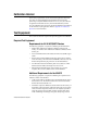
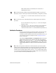
Appendix A: Calibration Options The complete calibration process for the NI 4070/4072 consists of verifying, adjusting, and reverifying a device. During verification, you compare the measured performance to an external standard of known measurement uncertainty to confirm that the product meets or exceeds specifications. Figure 4 shows the procedural flow for verification.
Table 23.
Go to Initial Setup Verify DC Voltage Mode? Yes Go to Verifying DC Voltage Yes Go to Verifying AC Voltage Yes Go to Verifying 4-Wire Resistance Yes Go to Verifying 2-Wire Resistance Yes Go to Verifying DC Current Yes Go to Verifying AC Current Yes Go to Verifying Frequency No Verify AC Voltage Mode? No Verify 4-Wire Resistance Mode? No Verify 2-Wire Resistance Mode? No Verify DC Current Mode? No Verify AC Current Mode? No Verify Frequency Mode? No Verify Capacitance and Inductance (NI 4072
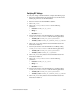
Verification Go to Adjusting DC Voltage and Resistance No Adjust AC Voltage Modes? Yes Go to Adjusting AC Voltage Modes No Adjust Current Modes? Yes Go to Adjusting Current Modes Go to Adjusting Capacitance and Inductance Perform Post-Adjustment Verification? Yes Go to Verification Procedures Flowchart No Go to Completing the Adjustment Procedures Figure 5.
Where to Go for Support The National Instruments Web site is your complete resource for technical support. At ni.com/support you have access to everything from troubleshooting and application development self-help resources to email and phone assistance from NI Application Engineers. A Declaration of Conformity (DoC) is our claim of compliance with the Council of the European Communities using the manufacturer’s declaration of conformity.