
Network Card User Manual


Chapter 4 Connecting Signals
© National Instruments Corporation 4-51 AT E Series User Manual
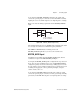
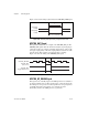
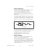
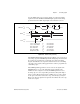
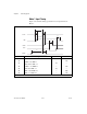
This section lists the timing specifications for handshaking with the
AT-MIO-16DE-10 port C circuitry. The handshaking lines STB* and IBF
synchronize input transfers. The handshaking lines OBF* and ACK*
synchronize output transfers.
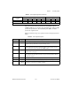
Table 4-8 summarizes the port C signals used in the timing diagrams that
follow.
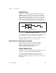
Mode 2 OBF
A
* ACK
A
* IBF
A
STB
A
* INTR
A
I/O I/O I/O
* Indicates that the signal is active low.
Table 4-8. Port C Signal Descriptions
Name Type Description
STB* Input Strobe Input—A low signal on this handshaking line loads data into the input latch.
IBF Output Input Buffer Full—A high signal on this handshaking line indicates that data has been
loaded into the input latch. This is an input acknowledge signal.
ACK* Input Acknowledge Input—A low signal on this handshaking line indicates that the data written
from the selected port has been accepted. This signal is a response from the external
device that it has received the data from the AT-MIO-16DE-10.
OBF* Output Output Buffer Full—A low signal on this handshaking line indicates that data has been
written from the selected port.
INTR Output Interrupt Request—This signal becomes high to request service during a data transfer.
The appropriate interrupt enable bits must be set to generate this signal and to allow it to
interrupt the computer.
RD* Internal Read Signal—This signal is the read signal generated by the host computer.
WR* Internal Write Signal—This signal is the write signal generated by the host computer.
DATA Input
or Output
Data Lines at the Selected Port (PA or PB)—This signal indicates when the data on the
data lines at a selected port is or should be available.
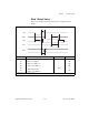
Table 4-7. Port C Signal Assignments (Continued)
Programming
Mode
Group A Group B
PC7 PC6 PC5 PC4 PC3 PC2 PC1 PC0