
Network Card User Manual


Chapter 4 Connecting Signals
AT E Series User Manual 4-6 ni.com
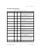
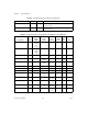
PA<0. .7 > DGND Input or
Output
Port A—These pins are port A of the extra digital I/O signals
on the AT-MIO-16DE-10.
PB<0..7> DGND Input or
Output
Port B—These pins are port B of the extra digital I/O signals
on the AT-MIO-16DE-10.
PC<0..7> DGND Input or
Output
Port C—These pins are port C of the extra digital I/O signals
on the AT-MIO-16DE-10.
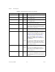
+5V DGND Output +5 VDC Source—Thesepinsarefusedforupto1Aof
+5 V supply. The fuse is self-resetting.
SCANCLK DGND Output Scan Clock—This pin pulses once for each A/D conversion
in the scanning modes when enabled. The low-to-high edge
indicates when the input signal can be removed from the
input or switched to another signal.
EXTSTROBE* DGND Output External Strobe—This output can be toggled under software
control to latch signals or trigger events on external devices.
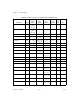
PFI0/TRIG1 DGND Input
Output
PFI0/Trigger 1—As an input, this is either one of the
Programmable Function Inputs (PFIs) or the source for
the hardware analog trigger. PFI signals are explained in
the Timing Connections section later in this chapter.
The hardware analog trigger is explained in the Analog
Trigger section of Chapter 3, Hardware Overview.
Analog trigger is available only on the AT-MIO-16E-1,
AT-MIO-16E-2, AT-MIO-16XE-10, AT-AI-16XE-10, and
the AT-MIO-64E-3.
As an output, this is the TRIG1 signal. In posttrigger data
acquisition sequences, a low-to-high transition indicates
the initiation of the acquisition sequence. In pretrigger
applications, a low-to-high transition indicates the initiation
of the pretrigger conversions.
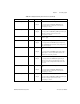
PFI1/TRIG2 DGND Input
Output
PFI1/Trigger 2—As an input, this is one of the PFIs.
As an output, this is the TRIG2 signal. In pretrigger
applications, a low-to-high transition indicates the initiation
of the posttrigger conversions. TRIG2 is not used in
posttrigger applications.
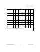
PFI2/CONVERT* DGND Input
Output
PFI2/Convert—As an input, this is one of the PFIs.
As an output, this is the CONVERT* signal. A high-to-low
edge on CONVERT* indicates that an A/D conversion is
occurring.
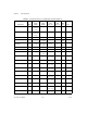
Table 4-2. I/O Signal Summary for the AT E Series (Continued)
Signal Name Reference Direction Description