
Network Card User Manual

Chapter 3 Hardware Overview
© National Instruments Corporation 3-13 AT E Series User Manual
Analog Output
♦ AT-MIO-16E-1, AT-MIO-16E-2, AT-MIO-64E-3, AT-MIO-16E-10, and
AT-MIO-16DE-10
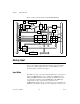
The AT E Series devices supply two channels of AO voltage at the I/O
connector. You can select the reference and range for the AO circuitry
through software. The reference can be either internal or external, whereas
the range can be either bipolar or unipolar.
♦ AT-MIO-16XE-50
The AT-MIO-16XE-50 supplies two channels of AO voltage at the I/O
connector. The range is fixed at bipolar ±10 V.
♦ AT-MIO-16XE-10
The AT-MIO-16XE-10 supplies two channels of AO voltage at the I/O
connector. The range is software selectable between unipolar (0 to 10 V)
and bipolar (+
10 V).
Analog Output Reference Selection
♦ AT-MIO-16E-1, AT-MIO-16E-2, AT-MIO-64E-3, AT-MIO-16E-10, and
AT-MIO-16DE-10 only
You can connect each D/A converter (DAC) to the AT E Series device
internal reference of 10 V or to the external reference signal connected
to the external reference (EXTREF) pin on the I/O connector. This signal
applied to EXTREF should be between –10 and +10 V. You do not need to
configure both channels for the same mode.
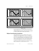
Analog Output Polarity Selection
♦ AT-MIO-16E-1, AT-MIO-16E-2, AT-MIO-64E-3, AT-MIO-16E-10, and
AT-MIO-16DE-10 only
You can configure each AO channel for either unipolar or bipolar output.
A unipolar configuration has a range of 0 to V
ref
at the AO. A bipolar
configuration has a range of –V
ref
to +V
ref
at the AO. V
ref
is the voltage
reference used by the DACs in the AO circuitry and can be either the
+10 Vonboard reference or an externally supplied reference between
–10 and +10 V. You do not need to configure both channels for the same
range.