
Network Card User Manual


Chapter 2 Installing and Configuring the Device
AT E Series User Manual 2-4 ni.com
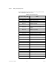
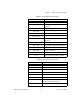
The following tables provide information concerning possible conflicts
when configuring the AT E Series device.
Table 2-1. PC AT I/O Address Map
I/O Address Range (Hex) Device
100 to 1EF —
1F0 to 1F8 IBM PC AT Fixed Disk
200 to 20F PC and PC AT Game Controller, reserved
210 to 213 PC-DIO-24 (default)
218 to 21F —
220 to 23F Previous generation of AT-MIO devices
(default)
240 to 25F AT-DIO-32F (default)
260 to 27F Lab-PC/PC+ (default)
278 to 28F AT Parallel Printer Port 2 (LPT2)
279 Reserved for Plug and Play operation
280 to 29F WD EtherCard+ (default)
2A0to2BF —
2E2to2F7 —
2F8to2FF PC,ATSerialPort2(COM2)
300 to 30F 3Com EtherLink (default)
310 to 31F —
320 to 32F ICMPC/XTFixedDiskController
330 to 35F —
360 to 363 PC Network (low address)
364 to 367 Reserved
368 to 36B PC Network (high address)
36C to 36F Reserved
370 to 366 PC, AT Parallel Printer Port 1 (LPT1)