
Network Card User Manual
Appendix A Specifications for AT-MIO-16XE-10 and AT-AI-16XE-10
© National Instruments Corporation A-27 AT E Series User Manual
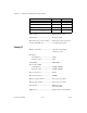
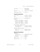
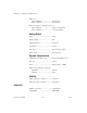
Triggers
Analog Trigger
Source..................................................... ACH<0..15>, PFI0/TRIG1
Level....................................................... ± Full-scale, internal;
±10 V, external
Slope....................................................... Positive or negative
(software selectable)
Resolution .............................................. 12 bits, 1 in 4,096
Hysteresis ............................................... Programmable
Bandwidth (–3 dB)................................. 255 kHz internal,
4 MHz external
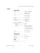
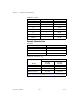
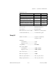
External input (PFI0/TRIG1)
Impedance....................................... 10 kΩ
Coupling.......................................... DC
Protection ........................................ –0.5toVcc+0.5Vwhen
configured as a digital signal
±35 V when configured as an
analog trigger signal or disabled
±35Vpoweredoff
Accuracy ................................................ ±1% of full-scale range
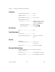
Digital Trigger
Compatibility ......................................... TTL
Response ................................................ Rising or falling edge
Pulse width............................................. 10 ns min
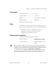
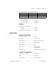
RTSI
Trigger Lines.......................................... 7