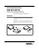
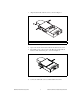
USER GUIDE AND SPECIFICATIONS USB-9211/9211A 4-Channel, 24-Bit Thermocouple Input Devices This user guide describes how to use the National Instruments USB-9211/9211A devices and lists the specifications. Introduction The NI USB-9211/9211A data acquisition device provides a USB interface for four channels of 24-bit thermocouple inputs with integrated signal conditioning. The NI USB-9211 consists of two components: an NI 9211 module and a USB-9161 carrier, as shown in Figure 1.
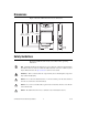
Dimensions Figure 2 shows the USB-9211/9211A device dimensions. Hi-Speed USB Carrier NI USB-9162 4.751 4.656 5.521 5.426 (120.68) (118.26) (140.23) (137.82) 3.469 (88.12) 0.998 (25.34) Figure 2. USB-9211/9211A Series Devices in Inches (Millimeters) Safety Guidelines Operate the USB-9211/9211A only as described in these operating instructions.
Safety Guidelines for Hazardous Voltages If hazardous voltages are connected to the module, take the following precautions. A hazardous voltage is a voltage greater than 42.4 Vpk or 60 VDC to earth ground. Ensure that hazardous voltage wiring is performed only by qualified personnel adhering to local electrical standards. Caution Caution Do not mix hazardous voltage circuits and human-accessible circuits on the same module.
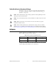
Related Documentation Guide Location NI-DAQmx Getting Started Guide Accessible from Start»All Programs» National Instruments»NI-DAQ after install. NI-DAQmx for USB Devices Getting Started Guide Ships with your device and, after install, is accessible from Start»All Programs» National Instruments»NI-DAQ. NI-DAQmx Base Getting Started Guide Accessible from Start»All Programs» National Instruments»NI-DAQmx Bases»Documentation after install. If your device uses NI-DAQmx Base, refer to ni.
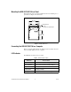
3. Align the I/O module with the carrier, as shown in Figure 3. 1 1 High Voltage Screw Terminal Backshell Figure 3. Module Installation 4. Squeeze the latches and insert the NI 9211 module into the carrier. 5. Press firmly on the connector side of the NI 9211 module until the latches lock the module into place, as shown in Figure 4. Figure 4. Locking Module into Place 6. © National Instruments Corporation Connect the USB cable to the assembled USB-9211/9211A.
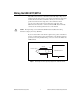
Mounting the USB-9211/9211A to a Panel Threaded inserts are located in the USB-9211/9211A for mounting it to a panel. Refer to Figure 5 for dimensions. 85.7 mm (3.37 in.) 72.2 mm (2.84 in.) Threaded Insert M3 x 0.5 8.5 mm (0.34 in.) Max Depth 76.1 mm (3.00 in.) Figure 5. Module Dimensions Connecting the USB-9211/9211A to a Computer Plug one end of the USB cable into the USB-9211/9211A and the other end into an available USB port on the computer. LED Indicator The LED indicator indicates device status.
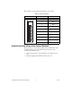
Wiring the USB-9211/9211A The USB-9211/9211A has a 10-terminal, detachable high voltage screw terminal enclosure that provides connections for four thermocouple input channels. Each channel has a terminal to which you can connect the positive lead of the thermocouple, TC+, and a terminal to which you can connect the negative lead of the thermocouple, TC–. The USB-9211/9211A also has a common terminal, COM, that is internally connected to the isolated ground reference of the module.
Refer to Table 3 for the terminal assignments for each channel. Table 3. Terminal Assignments Module Terminal Signal 0 TC0+ 1 TC0– 2 TC1+ 3 TC1– 4 TC2+ 4 5 5 TC2– 6 6 TC3+ 7 TC3– 8 No connection 9 Common (COM) 0 1 2 3 7 8 9 Assembling the High Voltage Screw Terminal Backshell The high voltage screw terminal backshell must be installed when using hazardous voltages (>42.4 Vpk, 60 VDC). Refer to Figure 7 while completing the following steps: 1.
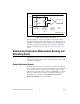
1 1 Strain Relief Figure 7. High Voltage Screw Terminal Backshell USB-9211/9211A Circuitry The USB-9211/9211A channels share a common ground that is isolated from the chassis and the host computer. Each channel has an impedance between the TC+ and COM terminals and between the TC– and COM terminals. Each channel is filtered and then sampled by a 24-bit analog-to-digital converter (ADC). There is a current source between the TC+ and TC– terminals.
TC+ 10 MΩ 10 MΩ TC– COM Input Impedance Open Thermocouple Detection Current Filtered Differential Amplifier Isolated ADC USB-9211/9211A Figure 8. Input Circuitry for One Channel If thermocouples are connected to the USB-9211/9211A, the gain and offset errors resulting from the source impedance of the thermocouples are negligible for most applications. Other voltage sources with a higher source impedance can introduce more significant errors.
Measurement Accuracy for the Different Types of Thermocouples Figures 9, 10, 11, 12, and 13 show the typical and maximum errors for the different thermocouple types when used with the USB-9211/9211A over the full temperature range. The figures also show the maximum error for the thermocouple types with the USB-9211/9211A at room temperature, 15 to 35 °C. The figures account for gain errors, offset errors, differential and integral nonlinearity, quantization errors, noise errors, and isothermal errors.
4 Max over Temp Range with Autozero Max at Room Temp Range without Autozero Typ over Temp Range with Autozero Error (°C) 3 2 1 0 –200 0 200 400 600 Measured Temperature (°C) 800 1000 Figure 10. Type E and T Errors 4 Error (°C) 3 2 1 0 Max over Temp Range with Autozero Max at Room Temp Range without Autozero Typ over Temp Range with Autozero –200 0 200 400 600 800 Measured Temperature (°C) 1000 1200 Figure 11. Type J and N Errors USB-9211/9211A User Guide and Specifications 12 ni.
4 Error (°C) 3 2 1 Max over Temp Range with Autozero Max at Room Temp Range without Autozero Typ over Temp Range with Autozero 0 –200 0 200 400 600 800 Measured Temperature (°C) 1000 1200 Figure 12. Type K Errors Error (°C) 6 4 2 Max over Temp Range with Autozero Max at Room Temp Range without Autozero Typ over Temp Range with Autozero 0 –200 0 200 400 600 800 1000 1200 Measured Temperature (°C) 1400 1600 Figure 13.
Minimizing Thermal Gradients Thermocouple wire can be a significant source of thermal gradients if it conducts heat or cold directly to terminal junctions. To minimize these errors, follow these guidelines: • Use small-gauge thermocouple wire. Smaller wire transfers less heat to or from the measuring junction. • Run thermocouple wiring together near the screw-terminal connector to keep the wires at the same temperature. • Avoid running thermocouple wires near hot or cold objects.
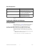
Cold-junction compensation sensor accuracy 0 to 60 °C ........................................ 0.6 °C (1.1 °F) typ, 1.3 °C (2.3 °F) max Conversion time ..................................... 70 ms per channel; 420 ms total for all channels including the autozero and cold-junction channels Max sampling rate (Hz) Type of Measurement Number of Channels in Scan List Tempertaure with CJC and Autozero Temperature with Autozero RAW Analog Input 1 4 6 12 2 3 4 6 3 2.4 3 4 4 2 2.
Offset error from source impedance .......0.05 µV typ, 0.07 µV max per Ω source impedance due to input current Power Requirements Current consumption from USB.............500 mA, max Suspend mode..................................2.5 mA, max Bus Interface USB specification USB-9211 ........................................USB 2.0 full speed USB-9211A .....................................USB 2.0 high speed Physical Characteristics If you need to clean the module, wipe it with a dry towel. Dimensions .......
Voltages Connect only voltages that are within these limits. Channel-to-COM ................................... ±30 V max, Measurement Category I Measurement Category I is for measurements performed on circuits not directly connected to the electrical distribution system referred to as MAINS voltage. MAINS is a hazardous live electrical supply system that powers equipment. This category is for measurements of voltages from specially protected secondary circuits.
Maximum altitude...................................2,000 m (at 25 °C ambient temperature) Pollution Degree (IEC 60664) ................2 Electromagnetic Compatibility Emissions................................................EN 55011 Class A at 10 m FCC Part 15A above 1 GHz Immunity ................................................EN 61326-1:1997 + A2:2001, Table 1 EMC/EMI ...............................................
Where to Go for Support The National Instruments Web site is your complete resource for technical support. At ni.com/support you have access to everything from troubleshooting and application development self-help resources to email and phone assistance from NI Application Engineers. National Instruments corporate headquarters is located at 11500 North Mopac Expressway, Austin, Texas, 78759-3504. National Instruments also has offices located around the world to help address your support needs.