OPERATING INSTRUCTIONS NI 9485 8-Channel Solid-State Relay (SSR) Digital Output Module
These operating instructions describe how to use the National Instruments 9485. For information about installing, configuring, and programming the system, refer to the system documentation. Visit ni.com/info and enter the info code rdsoftwareversion to determine which software you need for the modules you are using. The safety guidelines and specifications in this document are specific to the NI 9485. The other components in the system might not meet the same safety ratings and specifications.
Safety Guidelines for Hazardous Voltages If hazardous voltages are connected to the module, take the following precautions. A hazardous voltage is a voltage greater than 42.4 Vpk or 60 VDC to earth ground. Ensure that hazardous voltage wiring is performed only by qualified personnel adhering to local electrical standards. Caution Caution Do not mix hazardous voltage circuits and human-accessible circuits on the same module. When module terminals are hazardous voltage LIVE (>42.
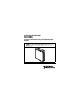
Figure 1 shows the NI 9939 connector backshell. Figure 1. NI 9939 Connector Backshell Safety Guidelines for Hazardous Locations The NI 9485 is suitable for use in Class I, Division 2, Groups A, B, C, D, T4 hazardous locations; Class I, Zone 2, AEx nA II T4 and Ex nA II T4 hazardous locations; and nonhazardous locations only. Follow these guidelines if you are installing the NI 9485 in a potentially explosive environment. Not following these guidelines may result in serious injury or death.
Caution Do not disconnect I/O-side wires or connectors unless power has been switched off or the area is known to be nonhazardous. Caution Do not remove modules unless power has been switched off or the area is known to be nonhazardous. Substitution of components may impair suitability for Class I, Division 2. Caution For Zone 2 applications, install the system in an enclosure rated to at least IP 54 as defined by IEC 60529 and EN 60529.
Special Conditions for Hazardous Locations Use in Europe This equipment has been evaluated as EEx nA II T4 equipment under DEMKO Certificate No. 03 ATEX 0324020X. The equipment is marked II 3G and is suitable for use in Zone 2 hazardous locations. Wiring the NI 9485 The NI 9485 has a 16-terminal, detachable screw-terminal connector that provides connections for eight solid-state relay channels. Each channel has two interchangeable terminals, CHa and CHb.
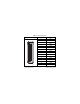
Table 1. Terminal Assignments Module Terminal 0 1 2 3 4 5 6 7 8 9 10 11 12 13 14 15 © National Instruments Corp.
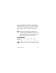
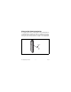
Wiring for High-Vibration Applications If an application is subject to high vibration, National Instruments recommends that you either use ferrules to terminate wires to the detachable screw-terminal connector or use the NI 9939 backshell kit to protect the connections. Refer to Figure 2 for an illustration. Ferrule Figure 2. 16-Pin Detachable Screw Terminal with Ferrule NI 9485 Operating Instructions 8 ni.
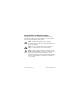
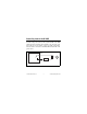
Connecting Loads to the NI 9485 You can connect loads to the NI 9485. Connect the load to one of the leads of the power source. Connect either the CHa or the CHb terminal to the load and the other terminal to the other lead of the AC or DC power source. Figure 3 shows a possible configuration where the load is connected to the CHb terminal and the DC or AC power source. CHa + or Load – AC CHb NI 9485 Figure 3. Connecting a Load to the NI 9485 © National Instruments Corp.
When you write an ON command to a channel, the SSR is closed and the terminal that is connected to the load allows current to flow or allows voltage to be applied to the load. When you write an OFF command to a channel, the switch opens, disconnecting the circuit so no current flows and no voltage is applied to the load.
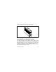
Figures 4 and 5 show examples of using an external flyback diode to protect DC inductive loads and an MOV to protect AC inductive loads, respectively. Flyback Diode for DC Inductive Loads CHa Inductive Load + – VDC CHb NI 9485 Figure 4. Contact Protection for DC Inductive Loads © National Instruments Corp.
MOV for AC Inductive Loads CHa Inductive Load VAC CHb NI 9485 Figure 5. Contact Protection for AC Inductive Loads Sleep Mode This module supports a low-power sleep mode. Support for sleep mode at the system level depends on the chassis that the module is plugged into. Refer to the chassis documentation for information about support for sleep mode. You can enable sleep mode in software. Refer to the driver software documentation for more information. NI 9485 Operating Instructions 12 ni.
Typically, when a system is in sleep mode, you cannot communicate with the modules. In sleep mode, the SSRs open to prevent current from flowing through the load. Consequently, the system consumes minimal power and may dissipate less heat than it does in normal mode. Refer to the Specifications section for more information about power consumption and thermal dissipation. Specifications The following specifications are typical for the range –40 to 70 °C unless otherwise noted.
Switching current, per channel1 All channels................................ 0.75 A max Up to four channels .................... 1.2 A max Switching rate (90% duty cycle)1 ..... 1 operation per second Relay open time ................................ 0.5 ms typ Relay close time................................ 9.0 ms typ On resistance..................................... 200 mΩ max Off state leakage ............................... 30 μA typ MTBF ...............................................
Power Requirements Power consumption from chassis Active mode ............................... 500 mW max Sleep mode ................................. 5 mW max Thermal dissipation (at 70 °C) Active mode ............................... 1.5 W max Sleep mode ................................. 5 mW max Physical Characteristics If you need to clean the module, wipe it with a dry towel. Screw-terminal wiring ...................... 12 to 24 AWG copper conductor wire with 10 mm (0.39 in.
Safety Safety Voltages Connect only voltages that are within these limits. Channel a-to-Channel b .................... 60 VDC max, 30 Vrms max Isolation Channel-to-channel Continuous ........................... 60 VDC Withstand ............................. 1,390 Vrms, verified by a 5 s dielectric withstand test Channel-to-earth ground Continuous ........................... 250 Vrms, Measurement Category II Withstand .............................
Safety Standards The NI 9485 is designed to meet the requirements of the following standards of safety for electrical equipment for measurement, control, and laboratory use: • IEC 61010-1, EN-61010-1 • UL 61010-1, CSA 61010-1 Note For UL and other safety certifications, refer to the product label or visit ni.com/certification, search by module number or product line, and click the appropriate link in the Certification column. Hazardous Locations U.S. (UL) ..........................................
Environmental National Instruments C Series modules are intended for indoor use only but may be used outdoors if installed in a suitable enclosure. Refer to the installation instructions for the chassis you are using for more information about meeting these specifications. Operating temperature (IEC 60068-2-1, IEC 60068-2-2) ..... –40 to 70 °C Storage temperature (IEC 60068-2-1, IEC 60068-2-2) ..... –40 to 85 °C Ingress protection.............................. IP 40 Operating humidity (IEC 60068-2-56)......
Shock and Vibration To meet these specifications, you must panel mount the system and either use ferrules to terminate wires to the detachable screw-terminal connector or use the NI 9939 backshell kit to protect the connections. Operating vibration Random (IEC 60068-2-34)......... 5 grms, 10 to 500 Hz Sinusoidal (IEC 60068-2-6) ....... 5 g, 10 to 500 Hz Operating shock (IEC 60068-2-27)..............................
Note For EMC compliance, operate this device according to product documentation. CE Compliance This product meets the essential requirements of applicable European Directives, as amended for CE marking, as follows: • 73/23/EEC; Low-Voltage Directive (safety) • 89/336/EEC; Electromagnetic Compatibility Directive (EMC) Note Refer to the Declaration of Conformity (DoC) for this product for any additional regulatory compliance information. To obtain the DoC for this product, visit ni.
National Instruments Contact Information The National Instruments Web site is your complete resource for technical support. At ni.com/support you have access to everything from troubleshooting and application development self-help resources to email and phone assistance from NI Application Engineers. National Instruments corporate headquarters is located at 11500 North Mopac Expressway, Austin, Texas, 78759-3504.
Korea 82 02 3451 3400, Lebanon 961 (0) 1 33 28 28, Malaysia 1800 887710, Mexico 01 800 010 0793, Netherlands 31 (0) 348 433 466, New Zealand 0800 553 322, Norway 47 (0) 66 90 76 60, Poland 48 22 3390150, Portugal 351 210 311 210, Russia 7 495 783 6851, Singapore 1800 226 5886, Slovenia 386 3 425 42 00, South Africa 27 0 11 805 8197, Spain 34 91 640 0085, Sweden 46 (0) 8 587 895 00, Switzerland 41 56 2005151, Taiwan 886 02 2377 2222, Thailand 662 278 6777, Turkey 90 212 279 3031, United Kingdom 44 (0) 1635 5
National Instruments, NI, ni.com, and LabVIEW are trademarks of National Instruments Corporation. Refer to the Terms of Use section on ni.com/legal for more information about National Instruments trademarks. Other product and company names mentioned herein are trademarks or trade names of their respective companies. For patents covering National Instruments products, refer to the appropriate location: Help»Patents in your software, the patents.txt file on your CD, or ni.com/patents.