Motion Control 7344/7334 Hardware User Manual 7344/7334 Hardware User Manual May 2001 Edition Part Number 322504B-01
Support Worldwide Technical Support and Product Information ni.
Important Information Warranty The 7344/7334 controllers are warranted against defects in materials and workmanship for a period of 1 year from the date of shipment, as evidenced by receipts or other documentation. National Instruments will, at its option, repair or replace equipment that proves to be defective during the warranty period. This warranty includes parts and labor.
Contents About This Manual Conventions ...................................................................................................................ix Related Documentation..................................................................................................x Chapter 1 Introduction About the 7344/7334 Controller ....................................................................................1-1 Features...................................................................................
Contents Onboard Programs (7344 only) ..................................................................................... 4-5 Host Communications ................................................................................................... 4-6 Chapter 5 Signal Connections Motion I/O Connector ................................................................................................... 5-1 Motion Axis Signals.....................................................................................
Contents Glossary Index Figures Figure 3-1. Figure 3-2. Figure 3-3. Figure 3-4. PCI-7344 Parts Locator Diagram ..........................................................3-1 PXI-7344 Parts Locator Diagram..........................................................3-2 FW-7344 Back Panel.............................................................................3-2 PCI-7334 Parts Locator Diagram ..........................................................3-3 Figure 4-1. Figure 4-2. Servo Axis Resources.......
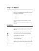
About This Manual This manual describes the electrical and mechanical aspects of each controller in the 7344/7334 family and contains information concerning their operation and programming. Unless otherwise noted, text applies to all controllers in the 7344/7334 family. The 7344/7334 family of controllers includes the following controllers: • PCI-7344 • PXI-7344 • FW-7344 • PCI-7334 The 7344/7334 controllers are designed for PCI, PXI, and 1394 bus computers.
About This Manual programs, subprograms, subroutines, device names, functions, operations, variables, filenames and extensions, and code excerpts. Related Documentation The following documents contain information that you might find helpful as you read this manual: • FlexMotion Software Reference Manual • FlexMotion Software Reference online help • FlexMotion VI online help • PCI Local Bus Specification, Revision 2.
1 Introduction This chapter describes the FlexMotion 7344 and 7334 controllers and their operation. About the 7344/7334 Controller Thank you for purchasing a 7344/7334 controller. The 7344/7334 controller features advanced motion control with easy-to-use software tools and add-on motion VI libraries for use with LabVIEW. Features The 7344 controllers are a combination of servo and stepper motor controllers for PCI, PXI, and 1394 bus computers.
Chapter 1 Introduction Hardware The high-performance capabilities of the 7344/7334 controllers are the result of an advanced dual-processor architecture using a Motorola MC68331 real-time 32-bit CPU combined with an Analog Devices ADSP-2185 digital signal processor (DSP) and custom field programmable gate arrays (FPGA).
Chapter 1 Introduction ❑ 7344/7334 Hardware User Manual ❑ FlexMotion Software Reference Manual ❑ One of the following software packages and documentation: – LabVIEW – LabWindows/CVI – FlexMotion software ❑ Your computer with an available PCI or PXI slot or a 1394 port, as appropriate. Software Programming Choices Programming your 7344/7334 controller is straightforward using a simple but powerful high-level function set application programming interface (API).
Chapter 1 Introduction Optional Equipment National Instruments offers a variety of products for use with the 7344/7334 controller, including cables, Universal Motion Interfaces (UMIs), drive power amplifier units, and other accessories as follows: • Cables and cable assemblies for motion and digital I/O • RTSI bus cables • UMI wiring connectivity blocks with integrated motion signal conditioning and motion inhibit functionality • Stepper and servo motor compatible driver amplifier units with integr
Configuration and Installation 2 This chapter describes how to configure and install your 7344/7334 controller. Software Installation Install your FlexMotion software, along with your Motion VI libraries (if appropriate) before you install the 7344/7334 controller. Refer to the release notes included with your 7344/7334 controller for specific instructions on the software installation sequence for your host PC.
Chapter 2 Configuration and Installation The following are general installation instructions, but consult your computer user manual or technical reference manual for specific instructions and warnings. 7344/7334 controllers are sensitive electronic devices shipped in an antistatic bag. Open only at an approved workstation and observe precautions for handling electrostatic-sensitive devices. Caution ♦ PCI-7344 and PCI-7334 1. Turn off and unplug your computer. 2.
Chapter 2 7. Visually verify the installation. 8. Plug in and turn on the chassis. Configuration and Installation Your PXI-7344 controller is installed. ♦ FW-7344 If you are not using the BP-1 battery pack, follow the instructions below. If you are using the BP-1 battery pack, follow the installation instructions in your BP-1 Battery Pack Installation Guide and then start with step 2 below. Note 1. Connect the power cord to the wall outlet and the FW-7344 controller. 2.
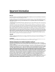
3 Hardware Overview This chapter presents an overview of the 7344/7334 controller hardware functionality. Figures 3-1, 3-2, and 3-4 show the PCI-7344, PXI-7344, and PCI-7334 parts locator diagrams, respectively. Figure 3-3 shows the FW-7344 back panel. 7 6 1 C 2 2001 5 3 4 1 2 3 RTSI Connector Assembly Number Label Serial Number Label 4 5 68-Pin Digital I/O Connector 68-Pin Motion I/O Connector 6 7 MC68331 CPU ADSP 2185 DSP Figure 3-1.
Chapter 3 Hardware Overview 1 2 6 5 4 1 2 Assembly Number Label Serial Number Label 3 3 4 ADSP 2185 DSP MC68331 CPU 5 6 68-Pin Digital I/O Connector 68-Pin Motion I/O Connector Figure 3-2. PXI-7344 Parts Locator Diagram 1 2 _ 3 4 5 + DIGITAL I/O NATIONAL INSTRUMENTS 1394 1 2 1394 Connectors Power Connector 3 4 9-25 VDC, 30W RTSI 6 MOTION I/O EXPANSION PORT RTSI Connector Expansion Port Connector 5 6 68-Pin Digital I/O Connector 68-Pin Motion I/O Connector Figure 3-3.
Chapter 3 Hardware Overview 7 6 1 C 2 5 2001 3 4 1 2 3 RTSI Connector Assembly Number Label Serial Number Label 4 5 68-Pin Digital I/O Connector 68-Pin Motion I/O Connector 6 7 MC68331 CPU ADSP 2185 DSP Figure 3-4.
Chapter 3 Hardware Overview The RTSI connector provides up to seven triggers and one high-speed clock signal to facilitate synchronization between multiple National Instruments products. Typical applications of the RTSI bus include triggering an image acquisition or DAQ measurement based on motion events, or capturing current motion positions based on events external to the motion controller. The RTSI bus can also be used for general-purpose I/O.
Functional Overview 4 This chapter presents an overview of the motion control algorithms and capabilities of the 7344/7334 controller. Dual Processor Architecture You can perform up to four axes of simultaneous, coordinated motion control in a preemptive, multitasking, real-time environment with the 7344/7334 controller.
Chapter 4 Functional Overview The DSP chip is a separate processor that operates independently from the CPU but is closely synchronized by an internal packet-based command, data, and messaging event structure. The 7344/7334 controllers are true multiprocessing and multitasking embedded controllers. The advanced architecture of the 7344/7334 controller enables advanced motion features, such as enhanced PID functions.
Chapter 4 Functional Overview Flash memory also allows objects such as programs and data arrays to be stored in non-volatile memory. It is possible to save the entire parameter state of the controller to the flash memory. On the next power cycle, the 7344/7334 controller automatically loads and returns the configuration to these new saved default values. The FPGA configuration programs are also stored in the flash ROM. Upon power-up, the FPGAs are booted with these programs.
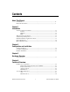
Chapter 4 Functional Overview 101100111 øA øB 32-Bit Encoder Interface Index 01011010 Stepper Control Loop 010010110 Stepper Pulse Generator 101100111 Figure 4-2. Stepper Axis Resources The 7344/7334 controller supports axes with secondary output resources (DACs for servo axes or stepper outputs). Defining two output resources is useful when controlling axes with multiple motors, such as gantry systems, where two DAC outputs can be configured with different torque limits and/or offsets.
Chapter 4 Functional Overview Onboard Programs (7344 only) The 7344 controller has full onboard programmability with the capability of executing up to 10 simultaneous motion programs in a real-time preemptive multitasking environment. This extremely powerful feature is designed for real-time applications that need tight synchronization and/or minimum latency—from a motion or other I/O event—and fast command execution. You can execute the entire FlexMotion function set from onboard programs.
Chapter 4 Functional Overview Host Communications The host computer communicates with a 7344/7334 controller through a number of memory port addresses on the host bus. The host bus can be any of the supported bus standards—PCI, PXI, or 1394. The primary bidirectional data transfer port is at the base address of the controller. This port supports FIFO data passing in both send and readback directions.
5 Signal Connections This chapter describes how to make input and output signal connections directly to the 7344/7334 and briefly describes the associated 7344/7334 I/O circuitry. The 7344/7334 has three connectors that handle all signals to and from the external motion system: • 68-pin motion I/O connector • 68-pin digital I/O connector • RTSI connector You can connect to your motion system with cables and accessories, varying from simple screw terminal blocks to enhanced UMI units and drives.
Chapter 5 Signal Connections Figure 5-1 shows the pin assignments for the 68-pin motion I/O connector on the 7344/7334 controller. A signal description follows the connector pinout. In this chapter, lines above signal names indicate that the signal is active-low.
Chapter 5 Signal Connections Table 5-1 describes the signals on the motion I/O connector. Table 5-1. Motion I/O Signal Connections Signal Name Reference Direction Axis <1..4> Dir (CCW) Digital Ground Output Motor direction or counter-clockwise control Axis <1..4> Step (CW) Digital Ground Output Motor step or clockwise control Axis <1..4> Encoder Phase A Digital Ground Input Closed-loop only—phase A encoder input Axis <1..
Chapter 5 Signal Connections Motion Axis Signals The following signals control the servo amplifier or stepper driver: • Analog Output <1..4> (7344 only)—These 16-bit DAC outputs are typically the servo command outputs for each axis. They can drive the industry-standard ±10 V output, and can be software limited to any positive or negative voltage range desired. They also feature a software-programmable voltage offset.
Chapter 5 • Signal Connections Axis <1..4> Inhibit—Use the inhibit output signals to control the enable/inhibit function of a servo amplifier or stepper driver. When properly connected and configured, the inhibit function causes the connected motor to be de-energized and its shaft turns freely. These open-collector inhibit signals feature 64 mA current sink capability with built-in 3.3 kΩ pull-up resistors to +5 V, and can directly drive most driver/amplifier inhibit input circuits.
Chapter 5 Signal Connections You can use software disabled limit and home inputs as general-purpose inputs. You can read the status of these inputs at any time and set and change their polarity as required. Limit and home inputs are a per axis enhancement on the 7344/7334 controllers and are not required for basic motion control. These inputs are part of a system solution for complete motion control.
Chapter 5 Signal Connections Encoder Signals The 7344/7334 controller offers four channels of single-ended quadrature encoder inputs. All National Instruments power drives and UMI accessories provide built-in circuitry that converts differential encoder signals to single-ended encoder signals. Each channel consists of a Phase A, a Phase B, and an Index input, as described in the following sections. Encoder<1..
Chapter 5 Signal Connections Encoder <1..4> Index The Index input is primarily used with the Find Index function. This function uses the number of counts per revolution (or linear distance) to initiate a search move that locates the index position. When a valid Index signal transition occurs during a Find Index sequence, the position of the Index signal is captured very accurately.
Chapter 5 Signal Connections Use of an unshielded cable can permit noise to corrupt the encoder signals resulting in lost counts and reduced motion system accuracy. Caution Encoder Input Circuit Figure 5-4 shows a simplified schematic diagram of the circuit used for the Phase A, Phase B, and Index encoder inputs. Both phases A and B are required for proper encoder counter operation, and the signals must support the 90° phase difference within system tolerance.
Chapter 5 Signal Connections edge. You can also use a trigger input as a latching general-purpose digital input by simply ignoring the captured position. • Shutdown Input—The shutdown input signal, when enabled in software, can be used to kill all motion by asserting the controller inhibits, setting the analog outputs to 0 V, and stopping any stepper pulse generation. To activate shutdown, the signal must transition from a low to high state (rising edge). • Breakpoint Output <1..
Chapter 5 Signal Connections Trigger Input, Shutdown Input, and Breakpoint Output Circuits Figures 5-5, 5-6, and 5-7 show a simplified schematic diagram of the circuits used by the trigger inputs, shutdown inputs, and breakpoint outputs for signal buffering. Vcc To the trigger circuits 3.3 kΩ 74HC244 1 kΩ 1/8 W From the external connector trigger pins DGND Figure 5-5. Trigger Input Circuit Vcc To the shutdown circuits 3.
Chapter 5 Signal Connections Analog Inputs The 7344/7334 controller has the following ADC input signals: • Analog Input <1..4>—The 7344/7334 controller includes an eight channel multiplexed, 12-bit ADC capable of measuring ±10 V, ±5 V, 0–10 V, and 0–5 V inputs. ADC channels 1 through 4 are brought out externally on the 68-pin motion I/O connector. ADC channels 5 through 8 are connected internally as shown in Table 5-2. These signals can be used for ADC test and calibration. Table 5-2.
Chapter 5 Signal Connections scan rate performance. Properly enabled, the scan rate is high enough to support analog feedback at the highest PID sample rate. • Analog Reference—For convenience, 7.5 V (nominal) analog reference voltage is made available. You can use this output as a low current supply to sensors that require a stable reference. • Analog Input Ground—To help keep digital noise out of the analog input, a separate return connection is provided.
Chapter 5 Signal Connections Digital I/O Connector All the general-purpose digital I/O lines on the 7344/7334 controllers are available on a separate 68-pin digital I/O connector. The pin assignments for this connector are shown in Figure 5-8.
Chapter 5 Signal Connections The 32-bit digital I/O port is configured in hardware as four 8-bit digital I/O ports. The bits in a port are typically controlled and read with byte-wide bitmapped commands. All digital I/O lines have programmable direction and polarity. Each output circuit can sink and source 24 mA. The state of the input pins at power-up is controlled by the DPull pin. Connecting DPull to +5 V or leaving it unconnected configures all pins in all ports for 100 kΩ pull-ups.
Chapter 5 Signal Connections RTSI Signal Considerations The 7344/7334 motion controllers allow you to use the RTSI signals as sources for trigger inputs, or as destinations for breakpoint outputs and encoder signals. The RTSI bus can also be used as a generic digital I/O port. Breakpoint outputs are output-only signals that generate an active-high pulse of 90−120 ns duration, as shown in Figure 5-9. tw tw = 90 - 120 ns Figure 5-9.
A Specifications This appendix lists the hardware and software performance specifications for the 7344/7334 controller. Servo Performance (7344 only) PID update rate range............................. 62.5 to 500 µs/sample Max PID update rate ....................... 62.5 µs/axis 4-axis PID update rate..................... 250 µs total Trajectory update rate ............................ Same as PID update rate Multi-axis synchronization ....................
Appendix A Specifications Feedforward (Aff, Vff) gains ..........0 to 32,767 Velocity feedback (Kv) gain ...........0 to 32,767 Servo command analog outputs Voltage range...................................±10 V Resolution........................................16 bits (0.000305 V/ LSB) Programmable torque (velocity) limits Positive limit ............................±10 V (–32,768 to +32,767) Negative limit...........................±10 V (–32,768 to +32,767) Programmable offset .......................
Appendix A Specifications Voltage range .................................. 0 to 5 V Output low voltage .................. < 0.6 V at 64 mA sink Output high voltage ................. Open collector with built-in 3.3 kΩ pull-up to +5 V Polarity............................................ Programmable, active-high or active-low System Safety Watchdog timer function ....................... Resets board to startup state Watchdog timeout........................... 63 ms Shutdown input Voltage range ...........
Appendix A Specifications Min pulse width...............................1 ms Control.............................................Individual enable/disable, stop on input, prevent motion, Find Home Trigger inputs Number of inputs.............................4 (Encoders 1 through 4) Voltage range...................................0 to 12 V Input low voltage......................0.8 V Input high voltage.....................2 V Polarity ............................................
Appendix A Specifications Analog inputs Number of inputs ............................ 8, multiplexed Number for user signals........... 4 Number for calibration ............ 4 Voltage range (programmable) ....... ±10 V, ±5 V, 0–10 V, 0–5 V Input resistance ............................... 10 kΩ min Resolution ....................................... 12 bits Analog reference output.................. 7.5 V (nominal) Reference drift ................................ ±30 ppm/°C typical INL.......................
Appendix A Specifications Polarity ............................................Programmable, active-high or active-low Outputs Voltage range...................................0 to 5 V Output low voltage ...................< 0.45 V at 24 mA sink Output high voltage..................> 2.4 V at 24 mA source Polarity ............................................Programmable, active-high or active-low PWM outputs Number of PWM outputs .........2 Max PWM frequency ...............32 kHz Resolution................
Appendix A Specifications Physical Dimensions (Not Including Connectors) PCI-7344/7334 ....................................... 17.5 by 9.9 cm (6.9 by 3.9 in.) PXI-7344................................................ 16 by 10 cm (6.3 by 3.9 in.) FW-7344 ................................................ 30.7 by 25.4 by 4.3 cm (12.1 by 10.0 by 1.7 in.) Connectors Motion I/O connector............................. 68-pin female high-density VHDCI type 32-bit digital I/O connector....................
B Cable Connector Descriptions This appendix describes the connector pinout for the cables that connect to your 7344/7334 boards. Figures B-1 and B-2 show the pin assignments for the stepper and servo 50-pin motion connectors. These connectors are available when you use the SH68-C68-S shielded cable assembly and the 68M-50F step/servo bulkhead cable adapter.
Appendix B Cable Connector Descriptions Analog Output Ground Digital Ground Digital Ground Axis 1 Home Switch Trigger/Breakpoint 1 Axis 1 Inhibit Analog Output Ground Digital Ground Digital Ground Axis 2 Home Switch Trigger/Breakpoint 2 Axis 2 Inhibit Analog Output Ground Digital Ground Digital Ground Axis 3 Home Switch Trigger/Breakpoint 3 Axis 3 Inhibit Analog Output Ground Digital Ground Digital Ground Axis 4 Home Switch Trigger/Breakpoint 4 Axis 4 Inhibit Digital Ground 1 3 5 7 9 11 13 15 17 19 21 23
Technical Support Resources C Web Support National Instruments Web support is your first stop for help in solving installation, configuration, and application problems and questions. Online problem-solving and diagnostic resources include frequently asked questions, knowledge bases, product-specific troubleshooting wizards, manuals, drivers, software updates, and more. Web support is available through the Technical Support section of ni.com . NI Developer Zone The NI Developer Zone at ni.
Appendix C Technical Support Resources Worldwide Support National Instruments has offices located around the world to help address your support needs. You can access our branch office Web sites from the Worldwide Offices section of ni.com. Branch office Web sites provide up-to-date contact information, support phone numbers, e-mail addresses, and current events.
Glossary Prefix Meanings Value p- pico- 10–12 n- nano- 10–9 µ- micro- 10– 6 m- milli- 10–3 c- centi 10–2 k- kilo- 10 3 M- mega- 10 6 Numbers/Symbols ° degrees / per % percent ± plus or minus + positive of, or plus – negative of, or minus Ω ohm +5 V +5 VDC source signal 1394 A high-speed external bus that implements the IEEE 1394 serial bus protocol © National Instruments Corporation G-1 7344/7334 Hardware User Manual
Glossary A A amperes A/D analog-to-digital absolute mode treat the target position loaded as position relative to zero (0) while making a move absolute position position relative to zero acceleration/ deceleration a measurement of the change in velocity as a function of time. Acceleration and deceleration describes the period when velocity is changing from one value to another.
Glossary Axis <1..4> Reverse Limit Input axis 1 through 4 reverse/counter-clockwise limit input B b bit—one binary digit, either 0 or 1 base address memory address that serves as the starting address for programmable or I/O bus registers. All other addresses are located by adding to the base address. binary a number system with a base of 2 buffer temporary storage for acquired or generated data (software) bus the group of conductors that interconnect individual circuitry in a computer.
Glossary D DAC Digital-to-Analog Converter DC direct current dedicated assigned to a particular function DGND digital ground signal digital I/O port a group of digital input/output signals DIP dual inline package DLL dynamic link library—provides the API for the motion control boards drivers software that communicates commands to control a specific motion control board DSP Digital Signal Processor E encoder device that translates mechanical motion into electrical signals; used for monito
Glossary following error trip point the difference between the instantaneous commanded trajectory position and the feedback position FPGA Field Programmable Gate Array freewheel the condition of a motor when power is de-energized and the motor shaft is free to turn with only frictional forces to impede it full-step full-step mode of a stepper motor—for a two phase motor this is done by energizing both windings or phases simultaneously G Gnd ground GND ground H half-step mode of a stepper motor
Glossary I/O input/output—the transfer of data to and from a computer system involving communications channels, operator interface devices, and/or motion control interfaces inverting the polarity of a switch (limit switch, home switch, and so on) in active state. If these switches are active-low they are said to have inverting polarity.
Glossary modulo position treat the position as within the range of total quadrature counts per revolution for an axis N noise an undesirable electrical signal—noise comes from external sources such as the AC power line, motors, generators, transformers, fluorescent lights, soldering irons, CRT displays, computers, electrical storms, welders, radio transmitters, and internal sources such as semiconductors, resistors, and capacitors. Noise corrupts signals you are trying to send or receive.
Glossary PWM Pulse Width Modulation—a method of controlling the average current in a motor phase winding by varying the on-time (duty cycle) of transistor switches PXI PCI eXtensions for Instrumentation Q quadrature counts the encoder line resolution times four R RAM random-access memory relative breakpoint sets the position breakpoint for an encoder in relative quadrature counts relative position destination or target position for motion specified with respect to the current location regardless
Glossary T toggle changing state from high to low, back to high, and so on torque force tending to produce rotation trapezoidal profile a typical motion trajectory, where a motor accelerates up to the programmed velocity using the programmed acceleration, traverses at the programmed velocity, then decelerates at the programmed acceleration to the target position trigger any event that causes or starts some form of data capture TTL transistor-transistor logic V V volts VCC positive voltage supp
Index Numbers axes overview, 4-3 to 4-4 servo axis resources (figure), 4-3 stepper axis resources (figure), 4-4 Axis<1..4> Dir (CCW) signal compatibility with third-party drives, 5-5 description (table), 5-3 purpose and use, 5-5 Axis<1..4> Encoder Index signal description (table), 5-3 purpose and use, 5-8 Axis<1..4> Encoder Phase A signal description (table), 5-3 purpose and use, 5-7 Axis<1..4> Encoder Phase B signal description (table), 5-3 purpose and use, 5-7 Axis<1..
Index B E breakpoint outputs output circuit (figure), 5-11 wiring concerns, 5-10 Breakpoint<1..4> signal description, 5-3 purpose and use, 5-10 embedded real-time operating system (RTOS), 4-1 to 4-2 encoder signals, 5-7 to 5-9 Axis<1..4> Encoder Index, 5-3, 5-8 Axis<1..4> Encoder Phase A, 5-3, 5-7 Axis<1..
Index motion I/O connector, 5-1 to 5-13 68-pin connector pin assignments (figure), 5-2 analog inputs, 5-12 to 5-13 signal descriptions, 5-12 to 5-13 wiring concerns, 5-13 encoder signals, 5-7 to 5-9 input circuit, 5-9 signal descriptions, 5-7 to 5-9 wiring concerns, 5-8 to 5-9 features, 5-1 limit and home inputs, 5-5 to 5-6 input circuit, 5-6 signal descriptions, 5-5 to 5-6 wiring concerns, 5-6 motion axis signals, 5-4 to 5-5 other connections, 5-13 overview, 1-4 signal connections (table), 5-3 signal desc
Index P software installation, 2-1 National Instruments application software, 1-3 onboard programs (7344 only), 4-5 programming choices, 1-3 specifications digital I/O, A-5 to A-6 environment, A-7 motion I/O, A-3 to A-5 physical, A-7 power requirements (max), A-6 RTSI trigger lines, A-6 servo performance, A-1 to A-2 stepper performance, A-2 to A-3 system safety, A-3 stepper axis resources (figure), 4-4 stepper performance specifications, A-2 to A-3 system integration, by National Instruments, C-1 system s
Index W Web support from National Instruments, C-1 wiring concerns analog inputs, 5-13 breakpoint outputs, 5-10 encoder signals, 5-8 to 5-9 limit and home inputs, 5-6 shutdown input, 5-10 trigger inputs, 5-10 Worldwide technical support, C-2 © National Instruments Corporation I-5 7344/7334 Hardware User Manual