Motion Control National Instruments 7340 User Manual NI 7340 User Manual November 2003 Edition Part Number 370838A-01
Support Worldwide Technical Support and Product Information ni.
Important Information Warranty The National Instruments 7340 is warranted against defects in materials and workmanship for a period of one year from the date of shipment, as evidenced by receipts or other documentation. National Instruments will, at its option, repair or replace equipment that proves to be defective during the warranty period. This warranty includes parts and labor.
Compliance FCC/Canada Radio Frequency Interference Compliance Determining FCC Class The Federal Communications Commission (FCC) has rules to protect wireless communications from interference. The FCC places digital electronics into two classes. These classes are known as Class A (for use in industrial-commercial locations only) or Class B (for use in residential or commercial locations). All National Instruments (NI) products are FCC Class A products.
Contents About This Manual Conventions ...................................................................................................................vii Related Documentation..................................................................................................viii Chapter 1 Introduction About the 7340 Controller .............................................................................................1-1 Features...........................................................................
Contents Onboard Programs and Buffers ..................................................................................... 4-5 Host Communications ................................................................................................... 4-5 Chapter 5 Signal Connections Motion I/O Connector ................................................................................................... 5-1 Motion Axis Signals.....................................................................................
About This Manual This manual describes the electrical and mechanical aspects of the PXI/PCI-7340 and contains information about how to operate and program the device. The 7340 is designed for PXI, Compact PCI, and PCI bus computers Conventions The following conventions appear in this manual: <> Angle brackets that contain numbers separated by an ellipsis represent a range of values associated with a bit or signal name—for example, DIO<3..0>.
About This Manual Related Documentation The following documents contain information you might find helpful as you read this manual: NI 7340 User Manual • NI-Motion User Manual • NI-Motion C Reference Help • NI-Motion VI Reference Help viii ni.
1 Introduction This chapter includes information about the features of the PXI/PCI-7340 controller and information about operating the device. About the 7340 Controller The 7340 controller features advanced motion control with easy-to-use software tools and add-on motion VI libraries for use with LabVIEW. Features The 7340 is a combination servo and stepper motor controller for PXI, Compact PCI, and PCI bus computers.
Chapter 1 Introduction powerful function set provide high-speed communications while off-loading complex motion functions from the host PC for optimum command throughput and system performance. With the 7340, you can use full onboard programming to execute up to 10 simultaneous motion programs. The 7340 features motion profiles that are controlled with enhanced PID/PIVff servo updates.
Chapter 1 Introduction Software Programming Choices NI-Motion is a simple but powerful high-level application programming interface (API) that makes programming the 7340 easy. All setup and motion control functions are easily executed by calling into a dynamically-linked library (DLL). You can call these libraries from C, Microsoft Visual Basic, and other high-level languages. Full function sets are available for LabVIEW, LabWindows/CVI, and other industry-standard software programs.
Chapter 1 Introduction For more specific information about these products, refer to the National Instruments catalog, the National Instruments Web site at ni.com, or call your National Instruments sales representative. Motion I/O Connections The external motion and digital I/O connectors on the 7340 are high-density, 68-pin female VHDCI connectors. For custom cables, use the AMP mating connector (part number 787801-1). NI 7340 User Manual 1-4 ni.
Configuration and Installation 2 This chapter describes how to configure and install the PXI/PCI-7340. Software Installation Before installing the 7340, install the NI-Motion driver software. Refer to the Getting Started with NI Motion Control manual, which is included with the controller, for specific installation instructions. If you do not install the NI-Motion driver software before attempting to use the 7340, the system does not recognize the 7340 and you are unable to configure or use the device.
Chapter 2 Configuration and Installation not use it until service-trained personnel can check its safety. If necessary, return the device to National Instruments for repair. Keep away from live circuits. Do not remove equipment covers or shields unless you are trained to do so. If signal wires are connected to the device, hazardous voltages can exist even when the equipment is turned off.
Chapter 2 Configuration and Installation Remove power from signal lines before connection to or disconnection from the device. Caution National Instruments measurement products may be classified as either Installation Category I or II. Operate products at or below the Installation Category level specified in the hardware specifications.
Chapter 2 Configuration and Installation meters and measurements on primary overcurrent protection devices and on ripple control units. Hardware Installation Install the 7340 in any open compatible expansion slot in the PXI or PCI system. Appendix A, Specifications, lists the typical power required for each controller. The following instructions are for general installation. Consult the computer user manual or technical reference manual for specific instructions and warnings.
Chapter 2 ♦ Configuration and Installation PCI-7340 1. Power off and unplug the computer. To protect yourself and the computer from electrical hazards, the computer must remain unplugged until the installation is complete. Caution 2. Remove the cover to expose access to the PCI expansion slots. 3. Choose an unused 5 V PCI slot, and remove the corresponding expansion slot cover on the back panel of the computer. 4.
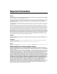
3 Hardware Overview This chapter presents an overview of the PXI/PCI-7340 hardware functionality. Figures 3-1 and 3-3 show the PXI-7340 and PCI-7340 parts locator diagrams, respectively. 1 5 4 3 1 2 3 Serial Number Label DSP CPU 2 4 5 68-Pin Digital I/O Connector 68-Pin Motion I/O Connector Figure 3-1. PXI-7340 Parts Locator Diagram Note The PXI-7340 assembly number is located on the back of the PXI module.
Chapter 3 Hardware Overview 1 1 2 2 Identification Number Used in Australia Symbol Indicating FFC Compliance 3 3 Symbol to Alert User to Read the Manual Figure 3-2.
Chapter 3 Hardware Overview User Connectors The 68-pin motion I/O connector provides all the signals for four axes of closed-loop motion control, including encoder feedback, limit and home inputs, breakpoint outputs, trigger inputs, digital-to-analog (DAC), and analog-to-digital (ADC) converter signals. Refer to Chapter 5, Signal Connections, for details about the signals in the motion I/O connector. The 68-pin digital I/O connector provides 32 bits of user-configurable digital I/O.
Functional Overview 4 This chapter provides an overview of motion control algorithms and the PXI/PCI-7340 controller. Dual Processor Architecture With the 7340, you can perform up to four axes of simultaneous, coordinated motion control in a preemptive, multitasking, real-time environment. An advanced dual-processor architecture that uses a 32-bit CPU combined with a digital signal processor (DSP) and custom FPGAs give the 7340 high-performance capabilities.
Chapter 4 Functional Overview Embedded Real-Time Operating System (RTOS) The embedded firmware is based on an embedded RTOS kernel and provides optimum system performance in varying motion applications. Motion tasks are prioritized. Task execution order depends on the priority of each task, the state of the entire motion system, I/O or other system events, and the real-time clock. The DSP chip is a separate processor that operates independently from the CPU but is closely synchronized.
Chapter 4 Functional Overview Flash Memory Nonvolatile memory on the 7340 is implemented with flash ROM, which means that the controllers can electrically erase and reprogram their own ROM. Because all the 7340 embedded firmware, including the RTOS and DSP code, is stored in flash memory, you can upgrade the onboard firmware contents in the field for support and new feature enhancement. Flash memory also allows objects such as programs and data arrays to be stored in non-volatile memory.
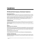
Chapter 4 Functional Overview 101100111 øA øB 32-Bit Encoder 0101011101101 Interface PID Servo Loop 11101101100 16-Bit D/A Converter ±10 V 101100111 Index Figure 4-1. Servo Axis Resources Trajectory Generator 101100111 øA 32-Bit Encoder Interface Optional 01011010 Stepper Control Loop 010010110 Stepper Pulse Generator 101100111 Index Figure 4-2. Stepper Axis Resources The 7340 supports axes with secondary output resources, such as DACs for servo axes or stepper outputs.
Chapter 4 Functional Overview If an encoder resource is not needed for axis control, you can use it for any number of other functions, including position or velocity monitoring, as a digital potentiometer encoder input, or as a master encoder input for master/slave (electronic gearing) applications. Each axis also has an associated forward and reverse limit input, a home input, a high-speed capture trigger input, a breakpoint output, and an inhibit output.
Chapter 4 Functional Overview The communications status register (CSR) provides bits for communications handshaking as well as real-time error reporting and general status feedback to the host PC. The move complete status (MCS) register provides instantaneous motion status of all axes. NI 7340 User Manual 4-6 ni.
5 Signal Connections This chapter describes how to make input and output signal connections directly to the PXI/PCI-7340 as well as general information about the associated I/O circuitry. The 7340 has three connectors that handle all signals to and from the external motion system.
Chapter 5 Signal Connections Figure 5-1 shows the pin assignments for the 68-pin motion I/O connector on the 7340. Table 5-1 includes descriptions for each of the signals. A line above a signal name indicates that the signal is active-low.
Chapter 5 Signal Connections Table 5-1 describes the signals on the motion I/O connector. Table 5-1. Motion I/O Signal Connections Signal Name Reference Direction Axis <1..4> Dir (CCW) Digital Ground Output Motor direction or counter-clockwise control Axis <1..4> Step (CW) Digital Ground Output Motor step or clockwise control Axis <1..4> Encoder Phase A Digital Ground Input Closed-loop only—phase A encoder input Axis <1..
Chapter 5 Signal Connections Motion Axis Signals The following signals control the servo amplifier or stepper driver. • Analog Output <1..4>—These 16-bit DAC outputs are typically the servo command outputs for each axis. They can drive the industry-standard ±10 V output, and can be software limited to any positive or negative voltage range. They also feature a software-programmable voltage offset.
Chapter 5 • Signal Connections Axis <1..4> Inhibit—Use the inhibit output signals to control the enable/inhibit function of a servo amplifier or stepper driver. When properly connected and configured, the inhibit function causes the connected motor to be de-energized and its shaft turns freely. These open-collector inhibit signals feature 64 mA current sink capability with built-in 3.3 kΩ pull-up resistors to +5 V, and can directly drive most driver/amplifier inhibit input circuits.
Chapter 5 Signal Connections You can use software disabled limit and home inputs as general-purpose inputs. You can read the status of these inputs at any time and set and change their polarity as required. Limit and home inputs are a per axis enhancement on the 7340 and are not required for basic motion control. These inputs are part of a system solution for complete motion control. National Instruments recommends using limits for personal safety, as well as to protect the motion system.
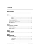
Chapter 5 Signal Connections Vcc 3.3 kΩ To the limit and home switch circuits 74FCT244 From the external connector limit and home switch pins 1 kΩ 1/8 W DGND Figure 5-2. Limit and Home Input Circuit Caution Excessive input voltages can cause erroneous operation and/or component failure. Verify that the input voltage is within the specification range. Encoder Signals The 7340 offers four channels of single-ended quadrature encoder inputs.
Chapter 5 Signal Connections of the relative signal phases provide distinct pulse edges that cause count up or count down pulses in the direction determined by the leading phase. A typical encoder with a specification of N (N = number) lines per unit of measure (revolutions or linear distance) produces 4 × N quadrature counts per unit of measure. The count is the basic increment of position in NI-Motion systems. Determine quadrature counts by multiplying the encoder resolution in encoder lines by four.
Chapter 5 Signal Connections Wiring Concerns The encoder inputs are connected to quadrature decoder/counter circuits. It is very important to minimize noise at this interface. Excessive noise on these encoder input signals may result in loss of counts or extra counts and erroneous closed-loop motion operation. Verify the encoder connections before powering up the system. Wire encoder signals and their ground connections separately from all other connections.
Chapter 5 Signal Connections Vcc To the quadrature decoder circuit 3.3 kΩ 74FCT244 From the external connector encoder input pins 1 kΩ 1/8 W DGND Figure 5-4. Encoder Input Circuit Trigger Inputs, Shutdown Input, and Breakpoint Outputs The 7340 offers additional high-performance features in the encoder FPGA. The encoder channels have high-speed position capture trigger inputs and breakpoint outputs.
Chapter 5 Signal Connections You can program breakpoints as absolute, modulo, or relative positions. Breakpoint outputs can be preset to a known state so that the transition when the breakpoint occurs can be low to high, high to low, or toggle. The breakpoint outputs are driven by open-collector TTL buffers that feature 64 mA sink current capability and built-in 3.3 kΩ pull-up resistors to +5 V. You can directly set and reset breakpoint outputs to use them as general-purpose digital outputs.
Chapter 5 Signal Connections Vcc To the shutdown circuits 3.3 kΩ 74FCT244 1 kΩ 1/8 W From the external connector shutdown pin DGND Figure 5-6. Shutdown Input Circuit Vcc 3.3 kΩ 74AS760 To the external connector breakpoint pins From the breakpoint circuits Figure 5-7. Breakpoint Output Circuit Analog Inputs The 7340 has the following ADC input signals: • Analog Input <1..4>—The 7340 includes an eight-channel multiplexed, 12-bit ADC capable of measuring ±10 V, ±5 V, 0–10 V, and 0–5 V inputs.
Chapter 5 Signal Connections You can configure each ADC channel for motion feedback, simple A/D conversion, or both. You can read the digital value of analog voltage on any of the eight ADC channels of the controller. Table 5-3 shows the range of values read back and the voltage resolution for each setting. The voltage resolution is in volts per least significant bit (V/LSB). Table 5-3. Analog Input Voltage Ranges Input Range Binary Values Resolution ±10 V –2,048 to 2,047 0.
Chapter 5 Signal Connections Other Motion I/O Connection The 7340 provides Host +5 V, which is the internal +5 V supply of the host computer. It is typically used to detect when the host computer is powered and to shut down external motion system components when the host computer is turned off or disconnected from the motion accessory.
Chapter 5 Signal Connections Digital I/O Connector All the general-purpose digital I/O lines on the 7340 are available on a separate 68-pin digital I/O connector. Figure 5-8 shows the pin assignments for this connector.
Chapter 5 Signal Connections The 32-bit digital I/O port is configured in hardware as four 8-bit digital I/O ports. The bits in a port are typically controlled and read with byte-wide bitmapped commands. All digital I/O lines have programmable direction and polarity. Each output circuit can sink and source 24 mA. The DPull pin controls the state of the input pins at power-up. Connecting DPull to +5 V or leaving it unconnected configures all pins in all ports for 100 kΩ pull-ups.
Chapter 5 Signal Connections RTSI Signal Considerations The 7340 motion controller allows you to use up to eight RTSI trigger lines as sources for trigger inputs, or as destinations for breakpoint outputs and encoder signals. The RTSI trigger lines also can serve as a generic digital I/O port. The RTSI star trigger line can be used only for a trigger input. Breakpoint outputs are output-only signals that generate an active-high pulse of 200 ns duration, as shown in Figure 5-9. 200 ns Figure 5-9.
A Specifications This appendix lists the hardware and software performance specifications for the PXI/PCI-7340. Hardware specifications are typical at 25 °C, unless otherwise stated. Servo Performance PID update rate range............................. 62.5 µs to 5 ms/sample Maximum PID update rate.............. 62.5 µs/axis 4-axis PID update rate..................... 250 µs total Multi-axis synchronization .................... <1 update sample Position accuracy Encoder feedback...........................
Appendix A Specifications Servo command analog outputs Voltage range...................................±10 V Resolution........................................16 bits (0.000305 V/LSB) Programmable torque (velocity) limits Positive limit ............................±10 V (–32,768 to +32,767) Negative limit...........................±10 V (–32,768 to +32,767) Programmable offset .......................±10 V (–32,768 to +32,767) Stepper Performance Trajectory update rate range ...................62.
Appendix A Specifications Voltage range .................................. 0 to 5 V Output low voltage .................. <0.6 V at 64 mA sink Output high voltage ................. Open collector with built-in 3.3 kΩ pull-up to +5 V Polarity............................................ Programmable, active-high or active-low System Safety Watchdog timer function ....................... Resets board to startup state Watchdog timeout........................... 63 ms Shutdown input Voltage range ............
Appendix A Specifications Minimum pulse width......................1 ms with filter enabled; 60 ns without filter enabled Control.............................................Individual enable/disable, stop on input, prevent motion, Find Home Trigger inputs Number of inputs.............................4 (Encoders 1 through 4) Voltage range...................................0 to 5 V Input low voltage......................0.8 V Input high voltage.....................2 V Polarity .............................
Appendix A Specifications Analog inputs Number of inputs ............................ 8, multiplexed, single ended Number for user signals........... 4 Number for system diagnostics ... 4 Voltage range (programmable) ....... ±10 V, ±5 V, 0–10 V, 0–5 V Input coupling ................................. DC Input resistance ............................... 10 kΩ min Resolution ....................................... 12 bits, no missing codes Monotonic .......................................
Appendix A Specifications PWM outputs Number of PWM outputs .........2 Maximum PWM frequency......50 kHz Resolution.................................8-bit Duty cycle range.......................0 to (255/256)% Clock sources ...........................Internal or external RTSI Trigger lines............................................8 Maximum Power Requirements +5 V (±3%).............................................1 A +12 V (±3%)...........................................30 mA –12 V (±3%) ...............
Appendix A Specifications Maximum Working Voltage Channel-to-earth..................................... 12 V, Installation Category I (signal voltage plus common-mode voltage) Channel-to-channel ................................ 22 V, Installation Category I (signal voltage plus common-mode voltage) These values represent the maximum allowable voltage between any accessible signals on the controller.
Appendix A Specifications Electromagnetic Compatibility Emissions................................................EN 55011 Class A at 10 m FCC Part 15A above 1 GHz Immunity ................................................EN 61326:1997 + A2:2001, Table 1 EMC/EMI ...............................................CE, C-Tick, and FCC Part 15 (Class A) Compliant Note For EMC compliance, you must operate this device with shielded cabling.
B Cable Connector Descriptions This appendix describes the connector pinout for the cables that connect to the PXI/PCI-7340. Figures B-1 and B-2 show the pin assignments for the stepper and servo 50-pin motion connectors. These connectors are available when you use the SH68-C68-S shielded cable assembly and the 68M-50F step/servo bulkhead cable adapter.
Appendix B Cable Connector Descriptions Analog Output Ground Digital Ground Digital Ground Axis 1 Home Switch Trigger/Breakpoint 1 Axis 1 Inhibit Analog Output Ground Digital Ground Digital Ground Axis 2 Home Switch Trigger/Breakpoint 2 Axis 2 Inhibit Analog Output Ground Digital Ground Digital Ground Axis 3 Home Switch Trigger/Breakpoint 3 Axis 3 Inhibit Analog Output Ground Digital Ground Digital Ground Axis 4 Home Switch Trigger/Breakpoint 4 Axis 4 Inhibit Digital Ground 1 3 5 7 9 11 13 15 17 19 21 23
Technical Support and Professional Services C Visit the following sections of the National Instruments Web site at ni.com for technical support and professional services: • Support—Online technical support resources include the following: – Self-Help Resources—For immediate answers and solutions, visit our extensive library of technical support resources available in English, Japanese, and Spanish at ni.com/support.
Appendix C Technical Support and Professional Services If you searched ni.com and could not find the answers you need, contact your local office or NI corporate headquarters. Phone numbers for our worldwide offices are listed at the front of this manual. You also can visit the Worldwide Offices section of ni.com/niglobal to access the branch office Web sites, which provide up-to-date contact information, support phone numbers, email addresses, and current events. NI 7340 User Manual C-2 ni.
Glossary Symbol Prefix Value µ micro 10– 6 m milli 10–3 M mega 10 6 Numbers/Symbols / per ± plus or minus + positive of, or plus – negative of, or minus +5 V +5 VDC source signal A A amperes A/D analog-to-digital absolute mode treat the target position loaded as position relative to zero (0) while making a move absolute position position relative to zero acceleration/ deceleration measurement of the change in velocity as a function of time.
Glossary address character code that identifies a specific location (or series of locations) in memory or on a host PC bus system amplifier drive that delivers power to operate the motor in response to low level control signals. In general, the amplifier is designed to operate with a particular motor type—for example, you cannot use a stepper drive to operate a DC brush motor Analog Input <1..4> 12-bit analog ADC input Analog Output <1..
Glossary byte eight related bits of data, an eight-bit binary number. Also used to denote the amount of memory required to store one byte of data.
Glossary E encoder device that translates mechanical motion into electrical signals; used for monitoring position or velocity in a closed-loop system encoder resolution number of encoder lines between consecutive encoder indexes (marker or Z-bit). If the encoder does not have an index output, the encoder resolution can be referred to as lines per revolution.
Glossary H half-step mode of a stepper motor—for a two phase motor this is done by alternately energizing two windings and then only one. In half step mode, alternate steps are strong and weak but there is significant improvement in low-speed smoothness over the full-step mode. hex hexadecimal home switch (input) physical position determined by the mechanical system or designer as the reference location for system initialization.
Glossary L LIFO last in, last out—data buffering technique where the newest values (last in) come out first limit switch/ end-of-travel position (input) sensors that alert the control electronics that physical end of travel is being approached and that the motion should stop M m meters MCS Move Complete Status microstep proportional control of energy in the coils of a Stepper Motor that allows the motor to move to or stop at locations other than the fixed magnetic/mechanical pole positions determi
Glossary O open-loop refers to a motion control system where no external sensors (feedback devices) are used to provide position or velocity correction signals P PCI Peripheral Component Interconnect—a high-performance expansion bus architecture originally developed by Intel to replace ISA and EISA. It is achieving widespread acceptance as a standard for PCs and workstations; it offers a theoretical maximum transfer rate of 132 MB/s.
Glossary relative position destination or target position for motion specified with respect to the current location regardless of its value relative position mode position relative to current position ribbon cable flat cable in which the conductors are side by side RPM revolutions per minute—units for velocity RPSPS or RPS/S revolutions per second squared—units for acceleration and deceleration RTR Ready to Receive S s seconds servo specifies an axis that controls a servo motor stepper spe
Glossary V V volts VCC positive voltage supply velocity mode move the axis continuously at the specified velocity W watchdog timer task that shuts down (resets) the motion control board if any serious error occurs word standard number of bits that a processor or memory manipulates at one time, typically 8-, 16-, or 32-bit © National Instruments Corporation G-9 NI 7340 User Manual
Index Numerics A 68-pin digital I/O connector, 3-3 motion I/O connector, 3-3 7340 analog feedback, 4-2 axes, 4-3 breakpoint outputs, 5-10 configuring, 2-1 embedded operating system, 4-2 encoder signals, 5-7 features, 1-1 flash memory, 4-3 general-purpose digital I/O lines, 5-15 hardware, 1-1 architecture, 4-1 home inputs, 5-5 input and output signal connections, 5-1 installing software, 2-1 introduction, 1-1 limit inputs, 5-5 motion I/O connections, 1-4 I/O connector, 5-1 resources, 4-4 National Instrumen
Index H motion I/O, 3-3, 5-1 motion I/O, 5-1 RTSI, 3-3, 5-1 conventions used in the manual, vii help, technical support, C-1 high-speed capture, 4-5 home inputs circuit, 5-7 ground connections, 5-6 Host +5 V, 5-14 host communications, 4-5 D Declaration of Conformity (NI resources), C-1 diagnostic tools (NI resources), C-1 documentation conventions used in manual, vii NI resources, C-1 related documentation, viii drivers (NI resources), C-1 I installing hardware, 2-4 installation category descriptions,
Index O T onboard programs, 4-5 technical support, C-1 training (NI resources), C-1 Trigger Input <1..