
Switch User Manual

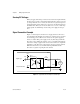
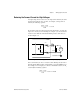
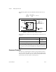
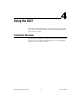
Table Of Contents
- 6527 User Manual
- Support
- Important Information
- Contents
- About This Manual
- Chapter 1 Getting Started with Your 6527
- Chapter 2 Installing and Configuring the 6527
- Chapter 3 Making Signal Connections
- Chapter 4 Using the 6527
- Appendix A Specifications
- Appendix B Technical Support Resources
- Glossary
- Index
Chapter 3 Making Signal Connections
© National Instruments Corporation 3-9 6527 User Manual
Reducing the Forward Current for High Voltages
As input voltage increases above 5 V, the input current drawn by the 6527
(forward current I
f
) also rises. At 24 V, for example, current per line is
found by the following equation:
If you wish to reduce the current and power the 6527 draws—to reduce the
impact on a circuit you are monitoring, for example—you can add another
resistor in series with the 3 kΩ current-limiting resistor on the 6527, as
showninFigure3-4.
Figure 3-4.
Reducing Input Current for High-Voltage Signals
It is recommended you choose a resistance value allowing at least 1 mA to
flow through the LED. Assume a maximum drop across the LED of 1.5 V.
For example, for 24 V inputs you could use a maximum resistance for R
s
asfoundbythefollowingequation:
24V 1.5V–()
3k
Ω
--------------------------------7.5mA=
0.25 W
6527
Isolation
3k
Load
DIG+
DIG–
Supply
Isolated Ground
R
s
I
f
+
24V 1.5V–()
1mA
--------------------------------3k
Ω
– 20 k
Ω
=