
Switch User Manual
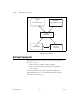

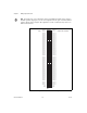

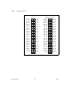
Table Of Contents
- 6527 User Manual
- Support
- Important Information
- Contents
- About This Manual
- Chapter 1 Getting Started with Your 6527
- Chapter 2 Installing and Configuring the 6527
- Chapter 3 Making Signal Connections
- Chapter 4 Using the 6527
- Appendix A Specifications
- Appendix B Technical Support Resources
- Glossary
- Index
Chapter 3 Making Signal Connections
© National Instruments Corporation 3-3 6527 User Manual
Cable Assembly Connectors
The optional R1005050 cable assembly you can use with the 6527 device
is an assembly of two 50-pin cables and three connectors. Both cables are
joined to a single connector on one end and to individual connectors on the
free ends. The 100-pin connector that joins the two cables plugs into the
I/O connector of the 6527 device. The other two connectors are 50-pin
connectors, one of which is connected to pins 1 through 50 and the other to
pins 51 through 100 of the 6527 device connector. Figure 3-2 shows the pin
assignments for the 50-pin connectors on the cable assembly.
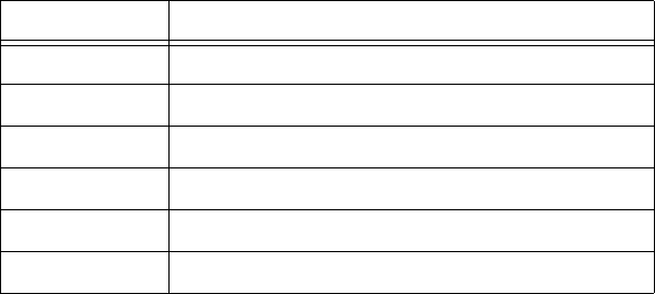
Table 3-1.
Port Functionality for 6527 Devices
Port Function
0 Input
1 Input
2 Input
3 Output with readback
4 Output with readback
5 Output with readback