
DAQ 6023E/6024E/6025E Multifunction I/O Devices User Manual
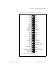
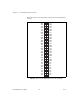
Table Of Contents
- 6023E/6024E/6025E User Manual
- Support
- Important Information
- Contents
- About This Manual
- Chapter 1 Introduction
- Chapter 2 Installation and Configuration
- Chapter 3 Hardware Overview
- Chapter 4 Signal Connections
- I/O Connector
- Analog Input Signal Overview
- Analog Input Signal Connections
- Analog Output Signal Connections
- Digital I/O Signal Connections
- Programmable Peripheral Interface (PPI)
- Power Connections
- Timing Connections
- Field Wiring Considerations
- Chapter 5 Calibration
- Appendix A Specifications
- Appendix B Custom Cabling and Optional Connectors
- Appendix C Common Questions
- Appendix D Technical Support Resources
- Glossary
- Index
- Figures
- Figure 1-1. The Relationship Between the Programming Environment, NI-DAQ, and Your Hardware
- Figure 3-1. PCI-6023E, PCI-6024E, PCI-6025E, and PXI-6025E Block Diagram
- Figure 3-2. DAQCard-6024E Block Diagram
- Figure 3-3. Dithering
- Figure 3-4. CONVERT* Signal Routing
- Figure 3-5. PCI RTSI Bus Signal Connection
- Figure 3-6. PXI RTSI Bus Signal Connection
- Figure 4-1. I/O Connector Pin Assignment for the 6023E/6024E
- Figure 4-2. I/O Connector Pin Assignment for the 6025E
- Figure 4-3. Programmable Gain Instrumentation Amplifier (PGIA)
- Figure 4-4. Summary of Analog Input Connections
- Figure 4-5. Differential Input Connections for Ground Referenced Signals
- Figure 4-6. Differential Input Connections for Nonreferenced Signals
- Figure 4-7. Single Ended Input Connections for Nonreferenced or Floating Signals
- Figure 4-8. Single Ended Input Connections for Ground Referenced Signals
- Figure 4-9. Analog Output Connections
- Figure 4-10. Digital I/O Connections
- Figure 4-11. Digital I/O Connections Block Diagram
- Figure 4-12. DIO Channel Configured for High DIO Power-up State with External Load
- Figure 4-13. Timing Specifications for Mode 1 Input Transfer
- Figure 4-14. Timing Specifications for Mode 1 Output Transfer
- Figure 4-15. Timing Specifications for Mode 2 Bidirectional Transfer
- Figure 4-16. Timing I/O Connections
- Figure 4-17. Typical Posttriggered Acquisition
- Figure 4-18. Typical Pretriggered Acquisition
- Figure 4-19. SCANCLK Signal Timing
- Figure 4-20. EXTSTROBE* Signal Timing
- Figure 4-21. TRIG1 Input Signal Timing
- Figure 4-22. TRIG1 Output Signal Timing
- Figure 4-23. TRIG2 Input Signal Timing
- Figure 4-24. TRIG2 Output Signal Timing
- Figure 4-25. STARTSCAN Input Signal Timing
- Figure 4-26. STARTSCAN Output Signal Timing
- Figure 4-27. CONVERT* Input Signal Timing
- Figure 4-28. CONVERT* Output Signal Timing
- Figure 4-29. SISOURCE Signal Timing
- Figure 4-30. WFTRIG Input Signal Timing
- Figure 4-31. WFTRIG Output Signal Timing
- Figure 4-32. UPDATE* Input Signal Timing
- Figure 4-33. UPDATE* Output Signal Timing
- Figure 4-34. UISOURCE Signal Timing
- Figure 4-35. GPCTR0_SOURCE Signal Timing
- Figure 4-36. GPCTR0_GATE Signal Timing in Edge Detection Mode
- Figure 4-37. GPCTR0_OUT Signal Timing
- Figure 4-38. GPCTR1_SOURCE Signal Timing
- Figure 4-39. GPCTR1_GATE Signal Timing in Edge Detection Mode
- Figure 4-40. GPCTR1_OUT Signal Timing
- Figure 4-41. GPCTR Timing Summary
- Figure B-1. 68 Pin E Series Connector Pin Assignments
- Figure B-2. 68 Pin Extended Digital Input Connector Pin Assignments
- Figure B-3. 50 Pin E Series Connector Pin Assignments
- Figure B-4. 50-Pin Extended Digital Input Connector Pin Assignments
- Tables
- Table 3-1. Available Input Configurations
- Table 3-2. Measurement Precision
- Table 3-3. Pins Used by PXI E Series Device
- Table 4-1. I/O Connector Details
- Table 4-2. I/O Connector Signal Descriptions
- Table 4-3. I/O Signal Summary
- Table 4-4. Port C Signal Assignments
- Table 4-5. Signal Names Used in Timing Diagrams

Appendix C Common Questions
6023E/6024E/6025E User Manual C-4 ni.com
24-bit counters (unlike the 16-bit counters on devices without the
DAQ-STC).
If you are using the NI-DAQ language interface or LabWindows/CVI, the
answer is no, the counter/timer applications that you wrote previously will
not work with the DAQ-STC. You must use the GPCTR functions; ICTR
and CTR functions will not work with the DAQ-STC. The GPCTR
functions have the same capabilities as the ICTR and CTR functions, plus
more, but you must rewrite the application with the GPCTR function calls.
I am using one of the general-purpose counter/timers on my device, but
I do not see the counter/timer output on the I/O connector. What am I
doing wrong?
If you are using the NI-DAQ language interface or LabWindows/CVI, you
must configure the output line to output the signal to the I/O connector. Use
the
Select_Signal
call in NI-DAQ to configure the output line. By
default, all timing I/O lines except EXTSTROBE* are high impedance.
What are the PFIs and how do I configure these lines?
PFIs are programmable function inputs. These lines serve as connections to
virtually all internal timing signals. If you are using the NI-DAQ language
interface or LabWindows/CVI, use the
Select_Signal
function to route
internal signals to the I/O connector, route external signals to internal
timing sources, or tie internal timing signals together.
If you are using NI-DAQ with LabVIEW and you want to connect external
signal sources to the PFI lines, you can use AI Clock Config, AI Trigger
Config, AO Clock Config, AO Trigger and Gate Config, CTR Mode
Config, and CTR Pulse Config advanced level VIs to indicate which
function the connected signal serves. Use the Route Signal VI to enable the
PFI lines to output internal signals.
Caution
If you enable a PFI line for output, do not connect any external signal source to it;
if you do, you can damage the device, the computer, and the connected equipment.
What are the power-on states of the PFI and DIO lines on the I/O
connector?
At system power-on and reset, both the PFI and DIO lines are set to high
impedance by the hardware. This means that the device circuitry is not
actively driving the output either high or low. However, these lines can have
pull-up or pull-down resistors connected to them as shown in Table 4-3, I/O
Signal Summary. These resistors weakly pull the output to either a logic
high or logic low state. For example, DIO(0) is in the high impedance state