
Welding System User Manual


Chapter 2 Function Reference — GPCTR_Set_Application
©
National Instruments Corporation 2-225 NI-DAQ FRM for PC Compatibles
When the counter reaches terminal count (2
24
– 1 for E Series and 445X devices, and 2
32
– 1
for 6602 and 455X devices), it rolls over and keeps counting. To check if this occurred, use
GPCTR_Watch function with entityID set to ND_TC_REACHED.
Typically, you will find modifying the following parameters through the
GPCTR_Change_Parameter function useful when the counter application is
ND_TRIG_PULSE_WIDTH_MSR. You can change the following:
•
ND_SOURCE to ND_INTERNAL_100_KHZ. With this timebase, you can measure pulse
widths between 20 µs and 160 s for E Series and 445X devices and pulse widths between
20 µs and 11.37 hours for 6602 and 455X devices. The timing resolution will be lower
than if you are using the
ND_INTERNAL_20_MHZ timebase.
•
ND_SOURCE_POLARITY to ND_HIGH_TO_LOW.
•
ND_GATE to any legal value listed in the GPCTR_Change_Parameter function
description.
•
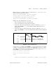
ND_GATE_POLARITY to ND_NEGATIVE. The pulse width will be measured from a
high-to-low to the next low-to-high transition of the gate signal.
You can use the
GPCTR_Change_Parameter function after calling
GPCTR_Set_Application and before calling GPCTR_Control with action = ND_PROGRAM
or
ND_PREPARE.
To provide your timebase, connect your timebase source to one of the source pins on the I/O
connector and change
ND_SOURCE and ND_SOURCE_POLARITY to the appropriate values.
You can also configure the other general-purpose counter for
ND_PULSE_TRAIN_GNR and set
ND_SOURCE of this counter to ND_OTHER_GPCTR_TC to generate pulses with delays and
measure interval pulse widths longer than 160 s for E Series and 445X devices. You can
generate pulse widths longer than 11.37 hours for 6602 and 455X devices by using this
application.
application =
ND_TWO_SIGNAL_EDGE_SEPARATION_MSR
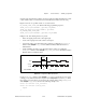
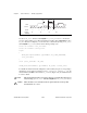
In this application, the counter is used for a single measurement of the time interval between
transitions of the gate and the second gate signal. Measurement starts when the gate signal is
asserted and stops when the second gate is asserted. By default, the measurement is performed
between low-to-high transitions of the gate and the second gate signals. The default values for
gate and second gate signals for the eight counters are shown in Table 2-25 and Table 2-26
respectively. The counter counts the 20 MHz internal timebase (
ND_INTERNAL_20_MHZ
),
so the resolution of measurement is 50 ns. The counter counts up starting from 0.
The default 20 MHz timebase, combined with the counter width (32 bits), lets you measure
the duration of a pulse between 100 ns and 214 s long.