
Network Card User Manual

Chapter 2 Installation and Verification
PCI Serial for Windows Me/9x 2-10 ni.com
DB-25 Connector
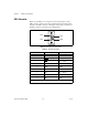
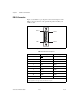
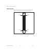
Figure 2-7 and Table 2-3 give the pin locations and descriptions of the
DB-25 connector, which is on the optional 10-position modular jack
to DB-25 cable.
Figure 2-7.
DB-25 Connector Pin Locations
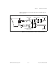
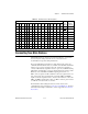
Table 2-3.
DB-25 Pin Descriptions
DB-25 Pin 232 Signal 485 Signal
2 TXD RTS+ (HSO+)
3 RXD CTS+ (HSI+)
4 RTS RTS- (HSO-)
5 CTS TXD+
6 DSR* CTS– (HSI–)
7 GND RXD–
8 DCD* GND
20 DTR* RXD+
22 RI* TXD–
Pins not listed in this table are No Connect.
* These signals are not supported by the isolated 232 ports.
PIN 1
PIN 25
PIN 13
PIN 14