OPERATING INSTRUCTIONS AND SPECIFICATIONS NI 9237 4-Channel, 24-Bit Half/Full-Bridge Analog Input Module Français Deutsch ni.
This document describes how to use the National Instruments 9237 and includes specifications and pin assignments for the NI 9237. Visit ni.com/info and enter rdsoftwareversion to determine which software you need for the modules you are using. For information about installing, configuring, and programming the system, refer to the system documentation. Visit ni.com/info and enter cseriesdoc for information about C Series documentation.
Safety Guidelines Operate the NI 9237 only as described in these operating instructions. This icon denotes that the component may be hot. Touching this component may result in bodily injury. Hot Surface Safety Guidelines for Hazardous Locations The NI 9237 is suitable for use in Class I, Division 2, Groups A, B, C, D, T4 hazardous locations; Class I, Zone 2, AEx nC IIC T4, and Ex nC IIC T4 hazardous locations; and nonhazardous locations only.
Substitution of components may impair suitability for Class I, Division 2. Caution For Zone 2 applications, install the system in an enclosure rated to at least IP 54 as defined by IEC 60529 and EN 60529. Caution Caution For Zone 2 applications, connected signals must be within the following limits: Capacitance .......................... 0.2 μF max Inductance ............................
Special Conditions for Marine Applications Some modules are Lloyd’s Register (LR) Type Approved for marine applications. To verify Lloyd’s Register certification, visit ni.com/certification and search for the LR certificate, or look for the Lloyd’s Register mark on the module. To meet radio frequency emission requirements for marine applications, use shielded cables and install the system in a metal enclosure.
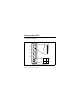
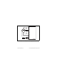
Connecting the NI 9237 The NI 9237 has four RJ-50 receptacles that provide connections for four half or full bridges. Ch0 – Ch3 1 2 3 4 5 6 7 8 9 10 Ch 0 Ch 1 Ch 2 SC AI+ AI– RS+ RS– EX+ EX– T+ T– SC Ch 3 EX+ EX+ EX– EX– Figure 1. NI 9237 Pin Assignments NI 9237 Operating Instructions and Specifications 6 ni.
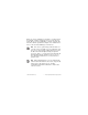
When you connect a half bridge to the NI 9237, you must connect the AI+, EX–, and RS– signals, but you do not connect the AI– signal. When you connect a full bridge, you must connect the AI+, AI–, EX–, and RS– signals. Refer to Figure 2 for an illustration of how to connect half and full bridges to the NI 9237. You can use a quarter bridge with the NI 9237 if you add a resistor externally to create a half bridge.
The NI 9237 has a four-terminal external excitation voltage source connector. You can use the EX+ and EX– terminals on the connector to connect one external excitation voltage source to the module. You can use the additional EX+ and EX– terminals on the connector to wire multiple NI 9237 modules together in a daisy chain.
RS+ EX+ AI+ AI– EX– RS– SC SC T+ TEDS T– NI 9237 Figure 2. Connecting a Half or Full Bridge to the NI 9237 © National Instruments Corp.
Each channel on the NI 9237 has an independent 24-bit ADC and an input amplifier that enable you to sample signals from all four channels simultaneously. The NI 9237 is isolated from earth ground. However, the individual channels are not isolated from each other. The EX+, EX–, and T– signals are common among all channels. You can connect the NI 9237 to a device that is biased at any voltage within the NI 9237 rejection range of earth ground.
Wiring TEDS Channels Ensure that neither the TEDS data (T+) nor the TEDS return (T–) signal is tied in common to any AI signals on the NI 9237. The NI 9237 connects all the T– signals together internally. Visit ni.com/info and enter the info code rdteds for more information about TEDS sensors. NI 9237 Connection Options Wiring resistance can create errors in bridge circuits. The NI 9237 provides two mechanisms to correct for these errors: remote sensing and shunt calibration.
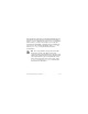
circuit. Refer to Figure 3 for an illustration of how to connect remote sense wires to the NI 9237. R lead R bridge RS+ EX+ R bridge AI+ AI– R bridge R bridge EX– R lead RS– NI 9237 Figure 3. Connecting Remote Sense Wires to the NI 9237 NI 9237 Operating Instructions and Specifications 12 ni.
The actual bridge excitation voltage is smaller than the voltage at the EX+ and EX– leads. If you do not use remote sensing of the actual bridge voltage, the resulting gain error is: R lead ----------------for half-bridge sensors and R bridge 2 ⋅ R lead ------------------- for full-bridge sensors. R bridge If you connect the remote sense signals directly to the bridge resistors, the NI 9237 senses the actual bridge voltage and eliminates the gain errors caused by the resistance of the EX+ and EX– leads.
sensors because there may be significant resistance in the wiring to the active resistor in the bridge. The NI 9237 shunt calibration circuitry consists of a precision resistor and a software-controlled switch. Refer to the software help for information about enabling the shunt calibration switch for the NI 9237. Shunt calibration involves simulating the input of strain by changing the resistance of an arm in the bridge by some known amount.
Excitation Voltages Although the sensor industry does not recognize a single standard excitation voltage level, excitation voltage levels of between 2.5 V and 10 V are common. You can program the NI 9237 to supply 2.5 V, 3.3 V, 5 V, or 10 V of excitation voltage, and the module can provide up to 150 mW of excitation power. Unless you supply external excitation voltage, National Instruments recommends that you set the excitation voltage to a value that keeps the total power below 150 mW.
The 150 mW limit allows you to power half and full bridges as follows: • Four 350 Ω half bridges at 5.0 V • Four 350 Ω full bridges at 3.3 V • Four 120 Ω half bridges at 2.5 V If you need an excitation voltage that causes more than 150 mW to dissipate across all the bridges, use the EX+ and EX– terminals on the external excitation voltage connector to connect an external excitation source to the NI 9237.
or signals that have been filtered by at least the amount of the stopband rejection. Passband The signals within the passband have frequency-dependent gain or attenuation. The small amount of variation in gain with respect to frequency is called the passband flatness. The digital filters of the NI 9237 adjust the frequency range of the passband to match the data rate. Therefore, the amount of gain or attenuation at a given frequency depends on the data rate.
0.025 Gain (dB) 0.000 –0.025 –0.050 0 0.1 0.2 0.3 0.4 0.5 Frequency/Data Rate Figure 4. Typical Passband Flatness for the NI 9237 Stopband The filter significantly attenuates all signals above the stopband frequency. The primary goal of the filter is to prevent aliasing. Therefore, the stopband frequency scales precisely with the data NI 9237 Operating Instructions and Specifications 18 ni.
rate. The stopband rejection is the minimum amount of attenuation applied by the filter to all signals with frequencies within the stopband. Alias-Free Bandwidth Any signal that appears in the alias-free bandwidth of the NI 9237 is not an aliased artifact of signals at a higher frequency. The alias-free bandwidth is defined by the ability of the filter to reject frequencies above the stopband frequency and equals the data rate minus the stopband frequency.
The following equation provides the available data rates of the NI 9237: f M ÷ 256 fs = --------------------n where n is any integer from 1 to 31. However, the data rate must remain within the appropriate data rate range. Refer to the Specifications section for more information about the data rate range. When using the internal master timebase of 12.8 MHz, the result is data rates of 50 kS/s, 25 kS/s, 16.67 kS/s, and so on down to 1.613 kS/s, depending on the value of n.
support for sleep mode. If the chassis supports sleep mode, refer to the software help for information about enabling sleep mode. Visit ni.com/info and enter cseriesdoc for information about C Series documentation. Typically, when a system is in sleep mode, you cannot communicate with the modules. In sleep mode, the system consumes minimal power and may dissipate less heat than it does in normal mode. Refer to the Specifications section for more information about power consumption and thermal dissipation.
Type of ADC..................................... Delta-Sigma (with analog prefiltering) Sampling mode ................................. Simultaneous Internal master timebase (fM) Frequency ................................... 12.8 MHz Accuracy..................................... ±100 ppm max Data rate range (fs) using internal master timebase Minimum.................................... 1.613 kS/s Maximum ................................... 50 kS/s Data rate range (fs) using external master timebase Minimum.
Overvoltage protection between any two pins........................ ±30 V Accuracy Percent of Reading (Gain Error) Percent of Range** (Offset Error) Calibrated typ (25 °C, ±5 °C) 0.05% 0.05% Calibrated max (–40 to 70 °C) 0.20% 0.25% Uncalibrated typ (25 °C, ±5 °C) 0.20% 0.1% Uncalibrated max (–40 to 70 °C) 0.60% 0.35% Measurement Conditions* * Before ** Range offset null or shunt calibration. equals 25 mV/V. Gain drift........................................... 10 ppm/°C max Offset drift 2.
Channel-to-channel matching (calibrated) Input Signal Frequency (fin) Gain Phase Typical Maximum Maximum 0 to 1 kHz 0.15% 0.3% 0.125°/kHz · fin 1 to 20 kHz 0.4% 1.1% Phase nonlinearity fin = 0 to 1 kHz............................ <0.001° fin = 0 to 20 kHz.......................... ±0.1° Input delay ........................................ 38.4/fs + 4.8 μs Passband Frequency ................................... 0.45 · fs Flatness....................................... 0.
Rejection at oversample rate1 fs = 10 kS/s.................................. 60 dB @ 640 kHz fs = 50 kS/s.................................. 90 dB @ 3.2 MHz Common-mode voltage, all signals to earth ground................. ±60 VDC CMRR Relative to earth ground2 (fin = 0 to 60 Hz) ......................... 140 dB Relative to EX– (fin = 0 to 1 kHz) ......................... 85 dB SFDR (1 kHz, –60 dBFS)................. 106 dB Total Harmonic Distortion (THD) 1 kHz, –20 dBFS ........................
Input noise Excitation Voltage Density (nV/Vrms per 1Hz ) Total, fin = 0 to 25 kHz (μV/Vrms) Total, fin = 0 to 1 kHz (nV/Vrms) 2.5 V 8 1.3 250 3.3 V 6 1.0 190 5V 4 0.6 130 10 V 2 0.3 65 Excitation noise ................................ 0.1 mV/Vrms Crosstalk fin = 1 kHz................................... 110 dB fin = 10 kHz................................. 100 dB Excitation Internal voltage........................... 2.5 V, 3.3 V, 5.0 V, 10.0 V Internal power.............................
Shunt calibration Resistance................................... 100 kΩ Resistor accuracy 25°C ..................................... ±110 Ω –40 to 70°C .......................... ±200 Ω MTBF ............................................... 603,359 hours at 25 °C; Bellcore Issue 2, Method 1, Case 3, Limited Part Stress Method Note Contact NI for Bellcore MTBF specifications at other temperatures or for MIL-HDBK-217F specifications. Power Requirements Power consumption from chassis Active mode ................
Physical Characteristics If you need to clean the module, wipe it with a dry towel. Weight............................................... 152 g (5.4 oz) Safety Safety Voltages Connect only voltages that are within the following limits. Between any two pins ....................... ±30 V max Isolation Channel-to-channel .................... None Channel-to-earth ground Continuous ........................... 60 VDC, Measurement Category I Withstand .............................
measurements of voltages from specially protected secondary circuits. Such voltage measurements include signal levels, special equipment, limited-energy parts of equipment, circuits powered by regulated low-voltage sources, and electronics. Do not connect the NI 9237 to signals or use for measurements within Measurement Categories II, III, or IV. Caution Hazardous Locations U.S. (UL) ..........................................
Safety Standards This product meets the requirements of the following standards of safety for electrical equipment for measurement, control, and laboratory use: • IEC 61010-1, EN 61010-1 • UL 61010-1, CSA 61010-1 Note For UL and other safety certifications, refer to the product label or the Online Product Certification section.
Note For the standards applied to assess the EMC of this product, refer to the Online Product Certification section. Note For EMC compliance, operate this device with shielded cabling.
Shock and Vibration To meet these specifications, you must panel mount the system. Operating vibration Random (IEC 60068-2-64)......... 5 grms, 10 to 500 Hz Sinusoidal (IEC 60068-2-6) ....... 5 g, 10 to 500 Hz Operating shock (IEC 60068-2-27).............................. 30 g, 11 ms half sine, 50 g, 3 ms half sine, 18 shocks at 6 orientations Environmental National Instruments C Series modules are intended for indoor use only but may be used outdoors if installed in a suitable enclosure.
Operating humidity (IEC 60068-2-56).............................. 10 to 90% RH, noncondensing Storage humidity (IEC 60068-2-56).............................. 5 to 95% RH, noncondensing Maximum altitude............................. 2,000 m Pollution Degree (IEC 60664) .......... 2 Environmental Management NI is committed to designing and manufacturing products in an environmentally responsible manner.
Waste Electrical and Electronic Equipment (WEEE) EU Customers At the end of the life cycle, all products must be sent to a WEEE recycling center. For more information about WEEE recycling centers and National Instruments WEEE initiatives, visit ni.com/ environment/weee. ⬉ᄤֵᙃѻક∵ᶧࠊㅵ⧚ࡲ⊩ ˄Ё RoHS˅ Ёᅶ᠋ National Instruments ヺড়Ё⬉ᄤֵᙃ ѻકЁ䰤ࠊՓ⫼ᶤѯ᳝ᆇ⠽䋼ᣛҸ (RoHS)DŽ݇Ѣ National Instruments Ё RoHS ড়㾘ᗻֵᙃˈ䇋ⱏᔩ ni.com/environment/rohs_chinaDŽ (For information about China RoHS compliance, go to ni.
Where to Go for Support The National Instruments Web site is your complete resource for technical support. At ni.com/support you have access to everything from troubleshooting and application development self-help resources to email and phone assistance from NI Application Engineers. National Instruments corporate headquarters is located at 11500 North Mopac Expressway, Austin, Texas, 78759-3504. National Instruments also has offices located around the world to help address your support needs.
Korea 82 02 3451 3400, Lebanon 961 (0) 1 33 28 28, Malaysia 1800 887710, Mexico 01 800 010 0793, Netherlands 31 (0) 348 433 466, New Zealand 0800 553 322, Norway 47 (0) 66 90 76 60, Poland 48 22 3390150, Portugal 351 210 311 210, Russia 7 495 783 6851, Singapore 1800 226 5886, Slovenia 386 3 425 42 00, South Africa 27 0 11 805 8197, Spain 34 91 640 0085, Sweden 46 (0) 8 587 895 00, Switzerland 41 56 2005151, Taiwan 886 02 2377 2222, Thailand 662 278 6777, Turkey 90 212 279 3031, United Kingdom 44 (0) 1635 5